Page 1172 of 4323
F13988
34
DI±970
± DIAGNOSTICSABS WITH EBD & BA & TRAC & VSC SYSTEM
1164 Author�: Date�:
2005 SEQUOIA (RM1146U)
INSPECTION PROCEDURE
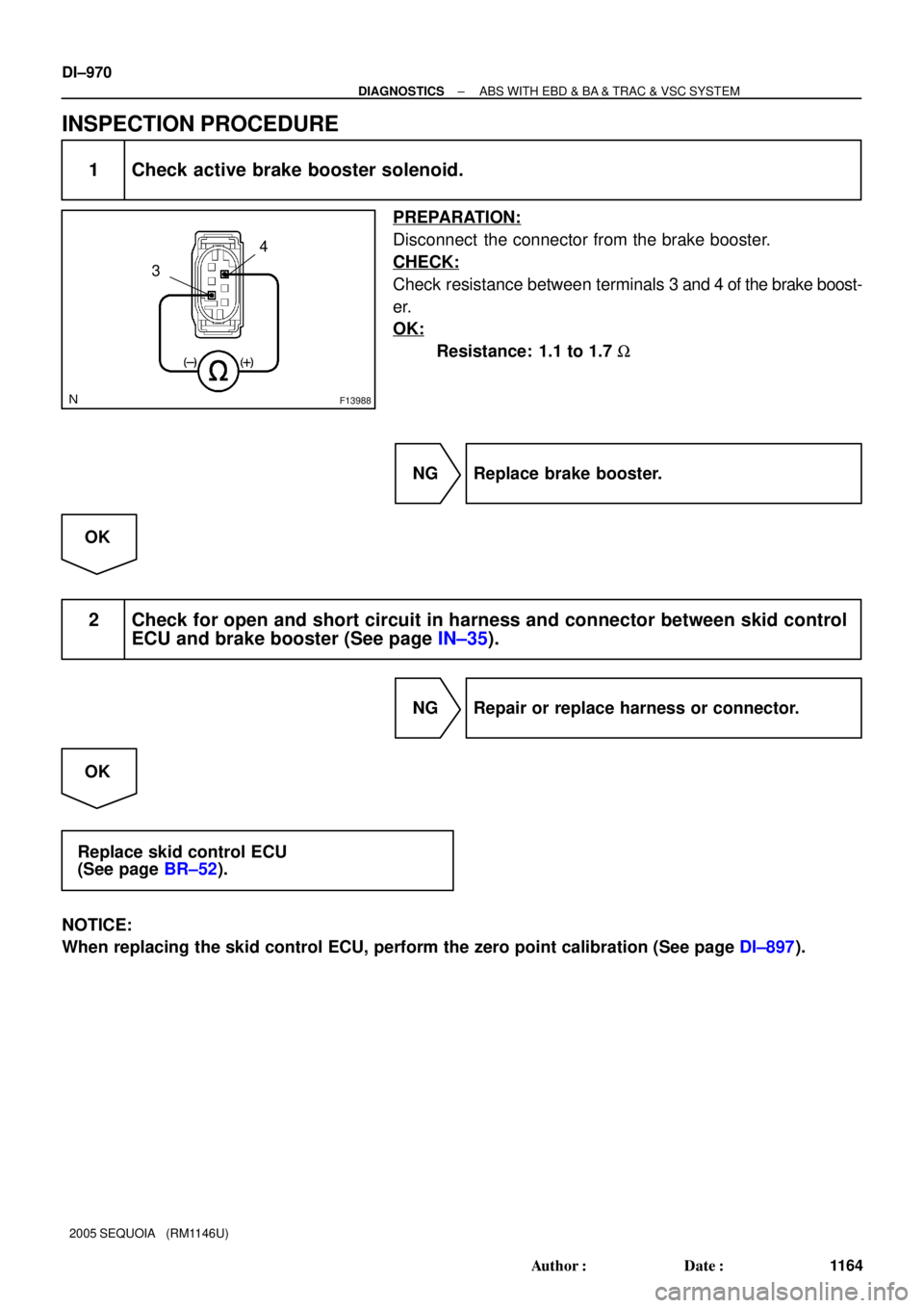
1 Check active brake booster solenoid.
PREPARATION:
Disconnect the connector from the brake booster.
CHECK:
Check resistance between terminals 3 and 4 of the brake boost-
er.
OK:
Resistance: 1.1 to 1.7 W
NG Replace brake booster.
OK
2 Check for open and short circuit in harness and connector between skid control
ECU and brake booster (See page IN±35).
NG Repair or replace harness or connector.
OK
Replace skid control ECU
(See page BR±52).
NOTICE:
When replacing the skid control ECU, perform the zero point calibration (See page DI±897).
Page 1173 of 4323
± DIAGNOSTICSABS WITH EBD & BA & TRAC & VSC SYSTEM
DI±971
1165 Author�: Date�:
2005 SEQUOIA (RM1146U)
DTC C1311 / 12 Open or Short Circuit in Brake Inhibit
Relay Circuit
CIRCUIT DESCRIPTION
Built in the stop lamp circuit and prohibits the stop lamp from turning on under VSC control.
DTC No.DTC Detecting ConditionTrouble Area
C1311 / 12Open or short circuit is detected.�Brake inhibit relay
�Brake inhibit relay circuit
DI93S±03
Page 1174 of 4323
F19773
ABS & VSC Actuator
(Skid Control ECU)
G±Y S14
Stop Light SW
I18 Ignition SW1 4 W
W±L
IG1
AM12
1
B±Y Instrument Panel J/B
2 1
1L
1F
1F1C
1C 1
2
46 STOP
AM1
ECU±IG W
4
B±R
Sub J/B No.3
3C8
3A8
B±R
B±R
J37AJ/C
J38AB8 Brake
Inhibit Relay
B±R L±OL±O
IL17
L±O
S1 38
BSW
STP S139
G±Y
IL2 13 12
3 4G±Y
4B1 1
14A
4C J11A
J10C J/C
CJ10G±Y G±W G±W
G±W
G±W B
J33
J34
H
G±W C
C
CJ44C
J45JR8 Rear Combination Light RH
1
4W±B
R7 Rear Combination Light LH
1
4 H9 High Mounted
Stop Light
A
A
A J19
J/C W±B
W±B
BD212
12W±B G±W
G±W
BD14
(*1) (*1)
(*2)(*2) W±B H9
High Mounted
Stop Light
1 2J57
J/C
BP BJ F10
Fusible
Link
Block ALT 8
5
B
Battery
*1: w/o Rear Spoiler
*2: w/ Rear Spoiler J/C
G±WJ/C
G±WSub J/B No.4
Stop Stop
DI±972
± DIAGNOSTICSABS WITH EBD & BA & TRAC & VSC SYSTEM
1166 Author�: Date�:
2005 SEQUOIA (RM1146U)
WIRING DIAGRAM
Page 1175 of 4323
F13968
ON
1
3
± DIAGNOSTICSABS WITH EBD & BA & TRAC & VSC SYSTEM
DI±973
1167 Author�: Date�:
2005 SEQUOIA (RM1146U)
INSPECTION PROCEDURE
1 Check voltage between terminals 1 and 3 of the brake inhibit relay and body
ground.
PREPARATION:
Remove the brake inhibit relay from the connector.
CHECK:
(a) Turn the ignition switch to the ON position.
(b) Measure the voltage between terminal 1 of the brake in-
hibit relay harness side connector and body ground.
OK:
Voltage: 10 to 14 V
CHECK:
Measure the voltage between terminal 3 of the brake inhibit
relay harness side connector and body ground when the brake
pedal is depressed.
OK:
Voltage: 8 to 14 V
NG Check and repair harness or connector.
OK
Page 1176 of 4323
F17285
1
2 34
1
4
3
2
DI±974
± DIAGNOSTICSABS WITH EBD & BA & TRAC & VSC SYSTEM
1168 Author�: Date�:
2005 SEQUOIA (RM1146U)
2 Check brake inhibit relay.
CHECK:
Check continuity between the following terminals of the brake
inhibit relay.
OK:
Terminals 1 and 2Continuity
(Reference value 62 W)
Terminals 3 and 4Continuity
CHECK:
(a) Apply battery positive voltage between terminals 1 and 2.
(b) Check continuity between terminals.
Terminals 3 and 4Open
NG Replace brake inhibit relay.
OK
3 Check for open and short circuit in harness and connector between brake inhibit
relay and skid control ECU (See page IN±35).
NG Repair or replace harness or connector.
OK
If the same code is still indicated after the DTC is deleted, check the condition of each connection.
If the connections are normal, the skid control ECU may be defective.
NOTICE:
When replacing the skid control ECU, perform the zero point calibration (See page DI±897).
Page 1186 of 4323

INSPECTION PROCEDURE
1 Is pedal lowered or spongy?
YES Bleed air from the system (See page BR�")
DI±984
± DIAGNOSTICSABS WITH EBD & BA & TRAC & VSC SYSTEM
1178 Author�: Date�:
2005 SEQUOIA (RM1146U)
INSPECTION PROCEDURE
1 Is pedal lowered or spongy?
YES Bleed air from the system (See page BR±4).
NO
2 Check output value of the master cylinder pressure sensor No. 1 and No. 2.
PREPARATION:
(a) Connect the hand±held tester to the DLC3.
(b) Turn the ignition switch to the ON position, and push the hand±held tester main switch ON.
(c) Select DATA LIST mode on the hand±held tester.
CHECK:
Check that the brake fluid pressure value of the master cylinder pressure sensor displayed on the hand±held
tester changes when depressing the brake pedal.
ItemMeasurement Item /
Range (Display)Normal ConditionDiagnostic Note
MAS CYL PRS 1
Master cylinder pressure
sensor 1 reading / min.: 0
V, max.: 5 VWhen brake pedal is re-
leased : 0.3 to 0.9 VReading increases when
brake pedal is depressed
MAS CYL PRS 2
Master cylinder pressure
sensor 1 reading / min.: 0
V, max.: 5 VWhen brake pedal is re-
leased : 0.3 to 0.9 VReading increases when
brake pedal is depressed
OK:
Brake fluid pressure value changes.
OK Go to step 4.
NG
3 Check for open and short circuit in harness and connector between master cyl-
inder pressure sensor and skid control ECU (See page IN±35).
NG Repair or replace harness or connector.
OK
Page 1193 of 4323
F14403F16959
A9
Booster Pedal
Force Switch
(ACTIVE Brake Booster)ABS & VSC Actuator
(Skid Control ECU)
STS
PSNC
PSNO5BR±Y
V±W
R±Y20
S1
18
21 S1
S1 2
1STS
PSNC
PSNO
± DIAGNOSTICSABS WITH EBD & BA & TRAC & VSC SYSTEM
DI±991
1185 Author�: Date�:
2005 SEQUOIA (RM1146U)
DTC C1363 / 63 Malfunction in Booster Pedal Force
Switch
CIRCUIT DESCRIPTION
Detects if the brake pedal is depressed.
DTC No.DTC Detecting ConditionTrouble Area
C1363 / 63Signal transmitted from booster pedal force switch to ECU
is abnormal.�Booster pedal force switch (Active brake booster)
�Booster pedal force switch (Active brake booster) circuit
WIRING DIAGRAM
DIDMF±01
Page 1194 of 4323
F19145
Yaw Rate
(Deceleration)
Sensor
STS
DI±992
± DIAGNOSTICSABS WITH EBD & BA & TRAC & VSC SYSTEM
1186 Author�: Date�:
2005 SEQUOIA (RM1146U)
INSPECTION PROCEDURE
1 Check voltage between terminal STS of brake pedal force switch and body
ground.
PREPARATION:
Disconnect the brake pedal force switch connector.
CHECK:
(a) Turn the ignition switch to the ON position.
(b) Measure the voltage between STS of brake pedal force
switch harness side connector and body ground.
OK:
Voltage: About 6 V
NG Go to step 3.
OK


G±Y S14
Stop Light SW
I18 Ignition SW1 4 W
W±L
IG1
AM12
1
B±Y Instrument Panel J/B
2 1
1L
1F
1F1C
1C 1
2
46 STOP
AM1
ECU±IG W
4
B±R
Sub J/B No.3
3C8")


ABS & VSC Actuator
(Skid Control ECU)
STS
PSNC
PSNO5BR±Y
V±W
R±Y20
S1
18
21 S1
S1 2
1STS
PSNC
PSNO
± DIAGNOSTICSABS WITH EBD & BA")