Page 1238 of 4323
F18069
DI±1036
± DIAGNOSTICSABS WITH EBD & BA & TRAC & VSC SYSTEM
1230 Author�: Date�:
2005 SEQUOIA (RM1146U)
3 Check harness and connector between translate ECU and parking brake switch
(See page BE±2).
NG Repair or replace parking brake switch circuit.
OK
4 Check brake fluid level warning switch.
PREPARATION:
Disconnect the brake fluid level warning switch connector.
CHECK:
Measure the resistance according to the value(s) in the table
below.
OK:
Tester ConnectionSwitch ConditionSpecified Condition
(B2±1) ± (B2±2)Float UP10 kW or more
(No continuity)
(B2±1) ± (B2±2)Float DOWN1 W or less (Continuity)
NG Replace brake fluid level warning switch.
OK
5 Check for open and short circuit in harness and connector between brake fluid
level warning switch and translate ECU (See page IN±35).
NG Repair or replace harness or connector.
OK
Page 1239 of 4323
± DIAGNOSTICSABS WITH EBD & BA & TRAC & VSC SYSTEM
DI±1037
1231 Author�: Date�:
2005 SEQUOIA (RM1146U)
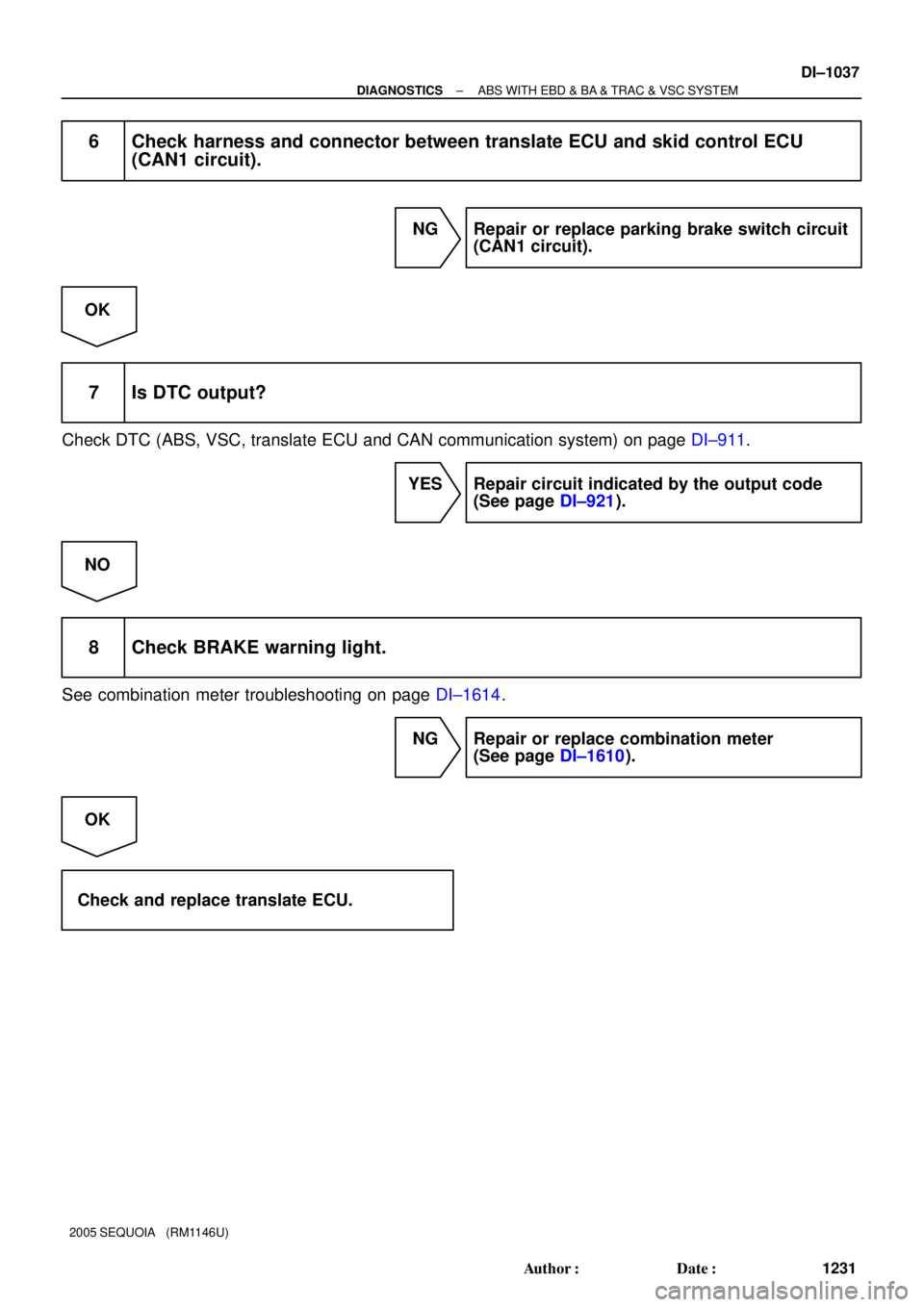
6 Check harness and connector between translate ECU and skid control ECU
(CAN1 circuit).
NG Repair or replace parking brake switch circuit
(CAN1 circuit).
OK
7 Is DTC output?
Check DTC (ABS, VSC, translate ECU and CAN communication system) on page DI±911.
YES Repair circuit indicated by the output code
(See page DI±921).
NO
8 Check BRAKE warning light.
See combination meter troubleshooting on page DI±1614.
NG Repair or replace combination meter
(See page DI±1610).
OK
Check and replace translate ECU.
Page 1240 of 4323
DI±1038
± DIAGNOSTICSABS WITH EBD & BA & TRAC & VSC SYSTEM
1232 Author�: Date�:
2005 SEQUOIA (RM1146U)
BRAKE Warning Light Circuit (Does not light up)
CIRCUIT DESCRIPTION
See page DI±1033.
WIRING DIAGRAM
See page DI±1033.
INSPECTION PROCEDURE
HINT:
Start the inspection from step 1 when using the hand±held tester and start from step 2 when not using the
hand±held tester.
1 Check operation of the BRAKE warning light.
PREPARATION:
(a) Connect the hand±held tester to the DLC3.
(b) Turn the ignition switch to the ON position and hand±held tester main switch ON.
(c) Select the ACTIVE TEST mode on the hand±held.
CHECK:
Check that ºONº and ºOFFº of the BRAKE warning light can be shown on the combination meter with the
hand±held tester.
ItemVehicle Condition/Test DetailsDiagnostic Note
BRAKE WARN LIGHTTurn BRAKE warning light ON/OFFObserve combination meter
OK:
BRAKE warning light operates.
NG Go to step 3.
OK
DIDMO±01
Page 1241 of 4323
± DIAGNOSTICSABS WITH EBD & BA & TRAC & VSC SYSTEM
DI±1039
1233 Author�: Date�:
2005 SEQUOIA (RM1146U)
2 Replace the translate ECU and check whether or not the trouble occurs again.
PREPARATION:
(a) Clear the DTC (See page DI±911).
(b) Turn the ignition switch OFF.
CHECK:
Turn the ignition switch to the ON position, and check if the same DTC still remains in the memory.
RESULT:
DTC is outputA
DTC is not outputB
B END.
A
Check and replace skid control ECU
(See page BR±52).
NOTICE:
When replacing the skid control ECU, perform the zero point calibration (See page DI±897).
3 Check harness and connector between translate ECU and skid control ECU
(CAN1 circuit).
NG Repair or replace parking brake switch circuit
(CAN1 circuit).
OK
4 Check harness and connector between translate ECU and combination meter
(See page IN±35).
NG Repair or replace harness or connector.
OK
Page 1242 of 4323
DI±1040
± DIAGNOSTICSABS WITH EBD & BA & TRAC & VSC SYSTEM
1234 Author�: Date�:
2005 SEQUOIA (RM1146U)
5 Check BRAKE warning light.
See combination meter troubleshooting on page DI±1614.
NG Repair combination meter assembly
(See page DI±1610).
OK
Check and replace skid control ECU
(See page BR±52).
NOTICE:
When replacing the skid control ECU, perform the zero point calibration (See page DI±897).
Page 1248 of 4323
DI±1046
± DIAGNOSTICSABS WITH EBD & BA & TRAC & VSC SYSTEM
1240 Author�: Date�:
2005 SEQUOIA (RM1146U)
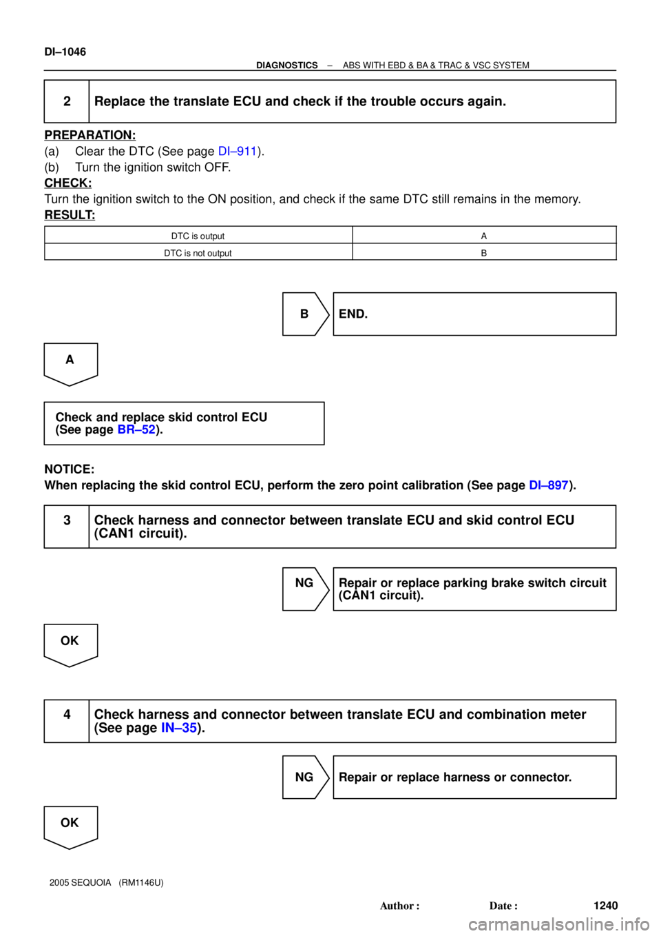
2 Replace the translate ECU and check if the trouble occurs again.
PREPARATION:
(a) Clear the DTC (See page DI±911).
(b) Turn the ignition switch OFF.
CHECK:
Turn the ignition switch to the ON position, and check if the same DTC still remains in the memory.
RESULT:
DTC is outputA
DTC is not outputB
B END.
A
Check and replace skid control ECU
(See page BR±52).
NOTICE:
When replacing the skid control ECU, perform the zero point calibration (See page DI±897).
3 Check harness and connector between translate ECU and skid control ECU
(CAN1 circuit).
NG Repair or replace parking brake switch circuit
(CAN1 circuit).
OK
4 Check harness and connector between translate ECU and combination meter
(See page IN±35).
NG Repair or replace harness or connector.
OK
Page 1255 of 4323

INSPECTION PROCEDURE
HINT:
Start the inspection from step 1 when using the hand±held tester")
± DIAGNOSTICSABS WITH EBD & BA & TRAC & VSC SYSTEM
DI±1053
1247 Author�: Date�:
2005 SEQUOIA (RM1146U)
INSPECTION PROCEDURE
HINT:
Start the inspection from step 1 when using the hand±held tester and start from step 2 when not using the
hand±held tester.
1 Check operation of the VSC buzzer.
PREPARATION:
(a) Connect the hand±held tester to the DLC3.
(b) Turn the ignition switch to the ON position and push the hand±held tester main switch ON.
(c) Select ACTIVE TEST mode on the hand±held tester.
CHECK:
Check ºON±OFFº function of the VSC buzzer with the hand±held tester.
ItemVehicle Condition / Test DetailsDiagnostic Note
VSC / BR WARN BUZTurns VSC / BRAKE warning buzzer ON / OFFBuzzer can be heard
OK:
Buzzer sound can be heard.
OK Replace skid control ECU
(See page BR±52).
NOTICE:
When replacing the skid control ECU, perform the zero
point calibration (See page DI±897).
NG
2 Check voltage between terminal 2 of the VSC buzzer and body ground.
PREPARATION:
Remove the VSC buzzer with connectors still connected.
CHECK:
(a) Turn the ignition switch to the ON position.
(b) Measure the voltage between terminal (2) of the VSC buzzer and body ground.
OK:
Voltage: 10 to 14 V
NG Repair or replace harness or connector from
voltage supply to VSC buzzer.
OK
Page 1257 of 4323
F19788
6
IL2
7 CANL
S12
VSC+ 6
TC 28Translate ECU
CANH11
VSC±
TC
CG
J43
J/CIG 4A55
4BP±B W
L ABS & VSC Actuator
(Skid Control ECU)
7
S1T5
T5
T5 W
L
IL2
P±B D6
Data Link Connector 3
O 13
4Sub J/B No. 4
O
AA (*) CAN1 Circuit
(*)
(*)
(*) (*)
± DIAGNOSTICSABS WITH EBD & BA & TRAC & VSC SYSTEM
DI±1055
1249 Author�: Date�:
2005 SEQUOIA (RM1146U)
Tc Terminal Circuit
CIRCUIT DESCRIPTION
Connecting terminals Tc and CG of the DLC3 causes the skid control ECU to indicate the DTC by blinking
the ABS warning light, VSC TRAC warning light and BRAKE warning light.
WIRING DIAGRAM
DI94B±04


7
S1T5
T5
T5 W
L
IL2
P±B D6
Data Link Connector 3
O 13
4Sub J/B No")