Page 1881 of 4323
DID98±01
I28587
From Battery Driving Position Memory Switch BODY ECU
Courtesy SW (D)
MM
Remote Control Mirror Switch
RHOuter
Mirror LH
(Retract
Motor) M1
M2 MM
M1 DCTY
PCTY
RRCY
RLCY
HCTY
KSW
LSWR
LSWL
PKB
WIG
IG
ACC
BECU
S+B
BDRACT+
ACTD
ACT±M2
MIRB
MIRS
MIRFM+
MSW
EB
MF
E2MR
Door Lock Motor
Front
LHFront
RHRear
LHRear
RH
Courtesy SW (P)
Courtesy SW (RR)
Courtesy SW (RL)
Hood Courtesy SW
Key Unlock Warning SW
Door Unlock Detection
SW Rear RH
Door Unlock Detection
SW Rear LH
Parking Brake SW
Battery AM1ALTACC IG1 Ignition SwitchWSH
ECU±IG
RAD No. 2
ECU±B
DOOR No. 2SECURITY
HORN AM1
± DIAGNOSTICSBODY CONTROL SYSTEM
DI±1679
1873 Author�: Date�:
2005 SEQUOIA (RM1146U)
SYSTEM DIAGRAM
Page 1889 of 4323

WIRELESS DOOR LOCK CONTROL
SymptomSuspected AreaSee page
All functions of wireless door lock control system do")
± DIAGNOSTICSBODY CONTROL SYSTEM
DI±1687
1881 Author�: Date�:
2005 SEQUOIA (RM1146U)
WIRELESS DOOR LOCK CONTROL
SymptomSuspected AreaSee page
All functions of wireless door lock control system do not operate.
1. Transmitter
2. Wireless door lock receiver circuit
3. Key unlock warning switch circuit
4. Body ECUBE±99
DI±1737
DI±1715
IN±35
Lock (or unlock) function does not operate.
1. Door unlock detection switch circuit (Driver's)
(Passenger's)
(Rear Door)
(Back Door)
2. Any door ECU
3. Body ECUDI±1791
DI±1829
DI±1723
DI±1869
IN±35
IN±35
Automatic lock function operates even if any door is opened within
30 seconds after all doors are unlocked by wireless door lock
control system.1. Door courtesy light switch circuit
2. Any door ECU
3. Body ECUDI±1728
IN±35
IN±35
Wireless door lock function operates, but the buzzer does not
sound.1. Wireless door lock buzzer circuit
2. Body ECUDI±1741
IN±35
Buzzer sounds, but wireless door lock function does not operate.Body ECUIN±35
REAR WIPER AND WASHER
SymptomSuspected AreaSee page
Rear wiper does not operate.1. Rear wiper switch and motor circuit
2. Body ECUDI±1704
IN±35
Rear washer does not operate.1. Rear washer switch and motor circuit
2. Body ECUDI±1704
IN±35
LIGHT CONTROL
SymptomSuspected AreaSee page
Automatic light control does not operate.
1. Automatic light control sensor circuit
2. Light control switch circuit
3. Body ECUDI±1753
DI±1750
IN±35
Auto turn±off does not operate.
1. Door courtesy light switch circuit (Driver side)
2. Ignition switch
3. Driver door ECU
4. Body ECUDI±1728
BE±24
IN±35
IN±35
Daytime running light function does not operate.
1. Daytime running light relay circuit
2. Parking brake switch circuit
3. Body ECUDI±1712
DI±1744
IN±35
FOG LIGHT
SymptomSuspected AreaSee page
Fog lights do not come on.
1. Bulb
2. FOG fuse
3. Fog light relay and switch circuit
4. Body ECU±
BE±14
DI±1710
IN±35
OTHERS
SymptomSuspected AreaSee page
Illuminated entry function does not operate.1. Illumination circuit
2. Body ECUDI±1759
IN±35
All functions of the body control system do not operate.1. Power source circuit
2. Body ECUDI±1700
IN±35
Remote control mirror does not operate.
(w/ Driving position memory)1. Remote control mirror switch circuit
2. Driving position memory switch circuit
3. Body ECUDI±1767
DI±1772
IN±35
Page 1893 of 4323
 TAIL ± GND1
(B6±7 ± B6±6)
G ± W±BLight control switch
(TAIL)Light control switch OFF10 to 14 V
CLTS (*3)")
± DIAGNOSTICSBODY CONTROL SYSTEM
DI±1691
1885 Author�: Date�:
2005 SEQUOIA (RM1146U) TAIL ± GND1
(B6±7 ± B6±6)
G ± W±BLight control switch
(TAIL)Light control switch OFF10 to 14 V
CLTS (*3) ± GND1
(B6±12 ± B6±6)Y ± W±BAutomatic light control
sensor (Signal)Ignition switch OFFBelow 1 V
CLTS (*3) ± GND1
(B6±12 ± B6±6)Y ± W±BAutomatic light control
sensor (Signal)Ignition switch ONSignal waveform
CLTE (*3) ± GND1
(B6±3 ± B6±6)BR ± W±BAutomatic light control
sensor (Ground)AlwaysBelow 1 V
CLTB (*3) ± GND1
(B6±4 ± B6±6)R±G ± W±BAutomatic light control
sensor (IG)Ignition switch OFFBelow 1 V
CLTB (*3) ± GND1
(B6±4 ± B6±6)R±G ± W±BAutomatic light control
sensor (IG)Ignition switch ON10 to 14 V
BZR ± GND1
(B7±15 ± B6±6)LG ± W±BWireless door lock
buzzer signalBuzzer does not soundBelow 1 V
BZR ± GND1
(B7±15 ± B6±6)LG ± W±BWireless door lock
buzzer signalBuzzer sounds10 to 14 V
RLD ± GND1
(B7±26 ± B6±6)L ± W±BPower window control
(Rear LH (DOWN))Ignition switch ONBelow 1 V
RLD ± GND1
(B7±26 ± B6±6)L ± W±BPower window control
(Rear LH (DOWN))Ignition switch ON,
Rear left power window DOWN
operation
10 to 14 V
RLU ± GND1
(B7±25 ± B6±6)G±R ± W±BPower window control
(Rear LH (UP))Ignition switch ONBelow 1 V
RLU ± GND1
(B7±25 ± B6±6)G±R ± W±BPower window control
(Rear LH (UP))Ignition switch ON,
Rear left power window UP op-
eration
10 to 14 V
RRD ± GND1
(B5±20 ± B6±6)L ± W±BPower window control
(Rear RH (DOWN))Ignition switch ONBelow 1 V
RRD ± GND1
(B5±20 ± B6±6)L ± W±BPower window control
(Rear RH (DOWN))Ignition switch ON,
Rear right power window DOWN
operation
10 to 14 V
RRU ± GND1
(B5±19 ± B6±6)G±Y ± W±BPower window control
(Rear RH (UP))Ignition switch ONBelow 1 V
RRU ± GND1
(B5±19 ± B6±6)G±Y ± W±BPower window control
(Rear RH (UP))Ignition switch ON,
Rear right power window UP op-
eration
10 to 14 V
HEAD ± GND1
(B6±9 ± B6±6)G±Y ± W±BLight control switch
(HEAD)Light control switch HEADBelow 1 V
HEAD ± GND1
(B6±9 ± B6±6)G±Y ± W±BLight control switch
(HEAD)Light control switch OFF or TAIL10 to 14 V
PKB ± GND1
(B5±3 ± B6±6)LG±R ± W±BParking brake switch
signalIgnition switch ON, Parking brake
appliedBelow 1 V
PKB ± GND1
(B5±3 ± B6±6)LG±R ± W±BParking brake switch
signalIgnition switch ON, Parking brake
not applied10 to 14 V
GSWGR RAirbag sensor commu-Airbag sensor communicationGSW
(B6±16)GR±RAirbag sensor commu
nication signal
Airbag sensor communication
circuit±
OBD2
(B5±2)G±RDiagnosis signalDLC3 communication circuit±
FFOG ± GND1
(B6±13 ± B6±6)G±B ± W±BFog light switch signalHeadlight dimmer switch LOW,
Fog light switch OFFBelow 1 V
Page 1896 of 4323

DATA LIST / ACTIVE TEST
1. DATA LIST
HINT:
According to the DATA LIST displayed by the hand±held tes")
DID99±01
DI±1694
± DIAGNOSTICSBODY CONTROL SYSTEM
1888 Author�: Date�:
2005 SEQUOIA (RM1146U)
DATA LIST / ACTIVE TEST
1. DATA LIST
HINT:
According to the DATA LIST displayed by the hand±held tester, you can read the values of the switches,
sensors, actuators and so on without parts removal. Reading the DATA LIST as a first step of troubleshooting
is one of the methods to shorten labor time.
(a) Connect the hand±held tester to the DLC3.
(b) Turn the ignition switch ON.
(c) According to the display on the tester, read the ºDATA LISTº.
BODY ECU:
ItemMeasurement Item/Display
(Range)Normal ConditionDiagnostic Note
KEY UNLK WRN SWKey unlock warning switch/ON or
OFFON: Key is in ignition key cylinder
OFF: No key is in ignition key cyl-
inder
±
ACC SWACC switch/ON or OFFON: Ignition switch ACC
OFF: Ignition switch OFF±
IG SWIG switch/ON or OFFON: Ignition switch ON
OFF: Ignition switch OFF±
PARKING BRAKE SWParking brake switch/ON or OFF
ON:
Parking brake pedal depressed
(ON)
OFF:
Parking brake released (OFF)
±
HOOD COURTSY SWHood courtesy switch/ON or OFF
ON: Engine hood OPEN
(Hood courtesy switch ON)
OFF: Engine hood CLOSED
(Hood courtesy switch OFF)
±
D DOR CTY SWDriver door courtesy light switch/
ON or OFFON: Driver door is opened
OFF: Driver door is closed±
P DOR CTY SWFront passenger door courtesy
light switch/ON or OFF
ON: Front passenger door is
opened
OFF: Front passenger door is
closed
±
Rr DOR CTY SWRear passenger door courtesy
light switch/ON or OFF
ON: Rear passenger door is
opened
OFF: Rear passenger door is
closed
±
MIRR SEL SW RRemote control mirror switch pas-
senger side/ON or OFF
ON: Remote control mirror switch
passenger side is selected
OFF: Remote control mirror switch
passenger side is not selected
±
MIRR SEL SW LRemote control mirror switch driv-
er side/ON or OFF
ON: Remote control mirror switch
driver side is selected
OFF: Remote control mirror switch
driver side is not selected
±
MIRR POS SW RRemote control mirror switch R
position/ON or OFF
ON: Remote control mirror switch
R position is selected
OFF: Remote control mirror switch
R position is not selected
±
Page 1901 of 4323
I28394
Parking Brake Switch
Door Lock Motor
Rear Power
Window Motor Courtesy Light
Switch
Courtesy LightRear Courtesy Light Switch Horn Switch
Stop Light Rear Room Light Front Map Light
Courtesy Light Rear Courtesy
Light Switch Door Lock Motor
Rear Power
Window MotorRear Window Control
Switch RH Door Lock Motor
Power Window Switch
� Passenger Door ECU
� Door Lock Control Switch
� Power Window Switch
Stop Light
Power Window
Master Switch
� Driver
Door ECU
� Door Lock
Control Switch
� Power
Window Switch
� Window Lock
Switch
Door Lock Motor
Rear Window
Control Switch LH
± DIAGNOSTICSBODY CONTROL SYSTEM
DI±1699
1893 Author�: Date�:
2005 SEQUOIA (RM1146U)
Page 1946 of 4323
I24358
Body ECU
P2
Parking
Brake SWPKB
14
B53
4
LG±R LG±RSub J/B No. 4
4D 4C DI±1744
± DIAGNOSTICSBODY CONTROL SYSTEM
1938 Author�: Date�:
2005 SEQUOIA (RM1146U)
Parking brake switch circuit
CIRCUIT DESCRIPTION
The body ECU determines if the parking brake switch is ON or OFF and sends the parking brake switch ON/
OFF signal to the combination meter via BEAN.
WIRING DIAGRAM
DI29Y±18
Page 1947 of 4323
± DIAGNOSTICSBODY CONTROL SYSTEM
DI±1745
1939 Author�: Date�:
2005 SEQUOIA (RM1146U)
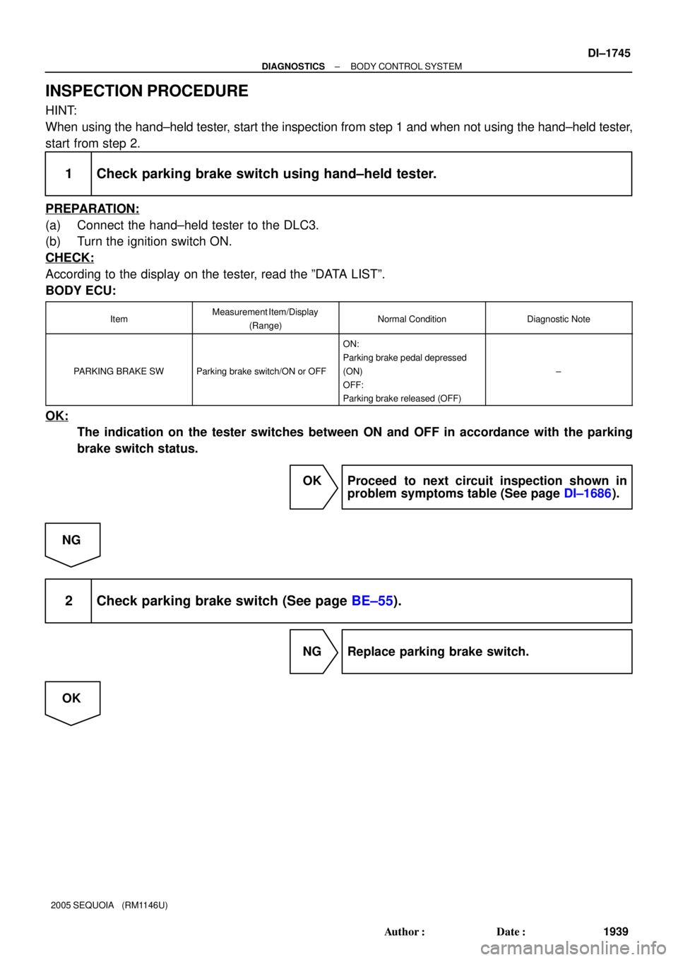
INSPECTION PROCEDURE
HINT:
When using the hand±held tester, start the inspection from step 1 and when not using the hand±held tester,
start from step 2.
1 Check parking brake switch using hand±held tester.
PREPARATION:
(a) Connect the hand±held tester to the DLC3.
(b) Turn the ignition switch ON.
CHECK:
According to the display on the tester, read the ºDATA LISTº.
BODY ECU:
ItemMeasurement Item/Display
(Range)Normal ConditionDiagnostic Note
PARKING BRAKE SWParking brake switch/ON or OFF
ON:
Parking brake pedal depressed
(ON)
OFF:
Parking brake released (OFF)
±
OK:
The indication on the tester switches between ON and OFF in accordance with the parking
brake switch status.
OK Proceed to next circuit inspection shown in
problem symptoms table (See page DI±1686).
NG
2 Check parking brake switch (See page BE±55).
NG Replace parking brake switch.
OK
Page 1948 of 4323
DI±1746
± DIAGNOSTICSBODY CONTROL SYSTEM
1940 Author�: Date�:
2005 SEQUOIA (RM1146U)
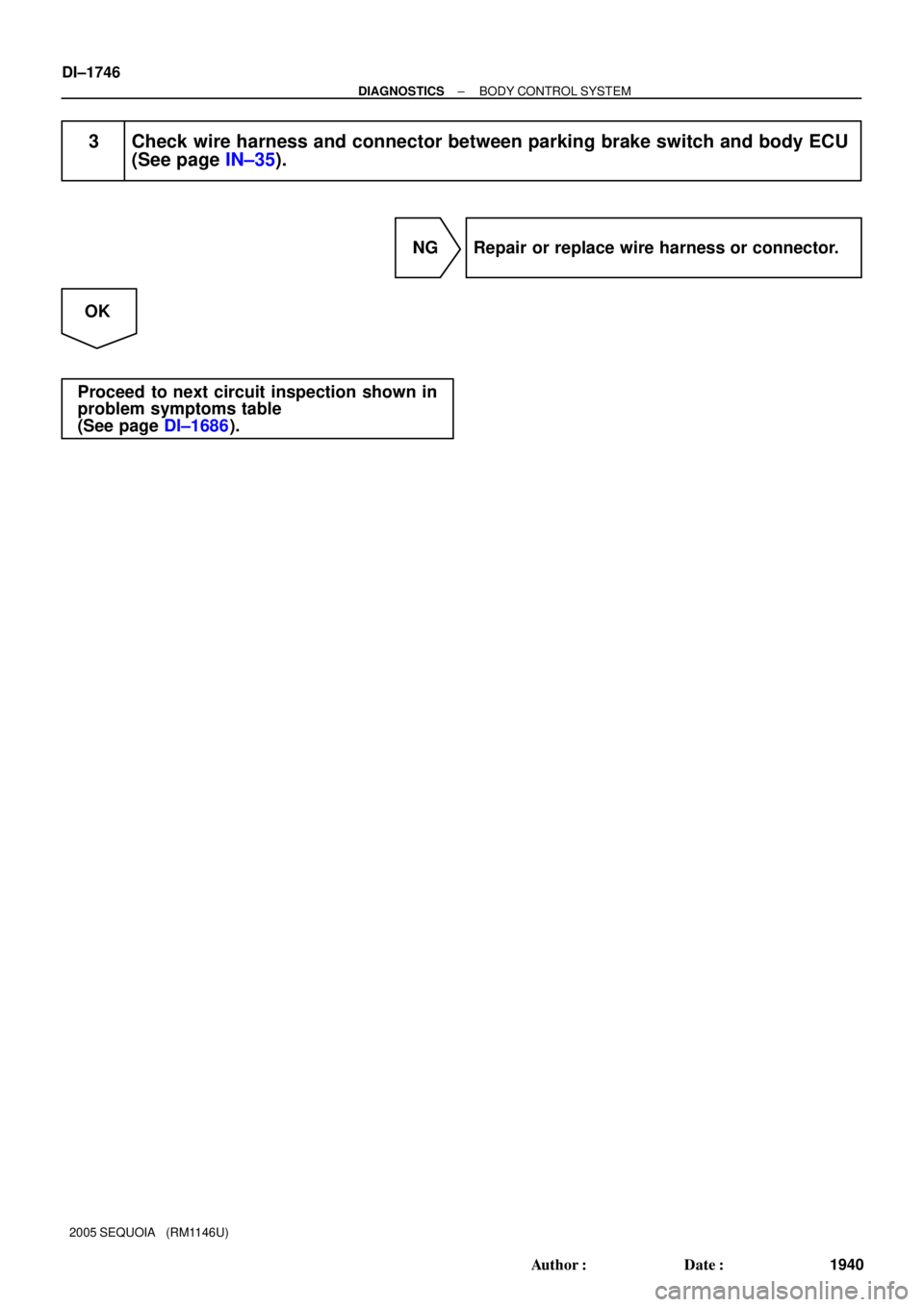
3 Check wire harness and connector between parking brake switch and body ECU
(See page IN±35).
NG Repair or replace wire harness or connector.
OK
Proceed to next circuit inspection shown in
problem symptoms table
(See page DI±1686).

MM
Remote Control Mirror Switch
RHOuter
Mirror LH
(Retract
Motor) M1
M2 MM
M1 DCTY
PCTY
RRCY
RLCY
HCTY
KSW
LSWR")