Page 1195 of 4323

5
(Oscilloscope)
ON
F17283
(Reference)IG ON Released Depressed
0 V
6 V
0 V 6 VPSNC±STS
PSNO±STS
F13990
5
21
ON
± DIAGNOSTICSABS WITH EBD & BA & TRAC & VSC SYSTEM
DI±993
11")
F13989
1
2(Oscilloscope)
5
(Oscilloscope)
ON
F17283
(Reference)IG ON Released Depressed
0 V
6 V
0 V 6 VPSNC±STS
PSNO±STS
F13990
5
21
ON
± DIAGNOSTICSABS WITH EBD & BA & TRAC & VSC SYSTEM
DI±993
1187 Author�: Date�:
2005 SEQUOIA (RM1146U)
2 Check booster pedal force switch.
When using the oscilloscope:
PREPARATION:
(a) Connect the oscilloscope between terminals PSNO(1)
and STS(5), PSNC(2) and STS(5) of the brake booster
with connector being connected.
(b) Turn the ignition switch to the ON position.
CHECK:
Check the signal waveform while the brake pedal is depressed
and released.
OK:
When not using the oscilloscope:
PREPARATION:
(a) Disconnect the connector from the brake booster.
(b) Turn the ignition switch to the ON position.
CHECK:
Check continuity between the terminals while depressing and
releasing the brake pedal.
OK:
Tester ConnectionConditionSpecified Condition
Terminals 2 ± 5ReleasedContinuity
Terminals 1 ± 5DepressedContinuity
NG Replace brake booster
(See page BR±22).
OK
Page 1204 of 4323
Translate
ECU
CANH
CANL6
2L
WL
W 7
IL2
6
IL27
T5
11
T5VSC+
VSC±
IG1 1
T5 B±R
J37 J37J/C
B±R
B±R8
3C 8
3A
I18
Ignition SW
4
1F4
1C
1L6
1C ECU±IG
AM")
F19197
S1 ABS & VSC Actuator
(Skid Control ECU)Translate
ECU
CANH
CANL6
2L
WL
W 7
IL2
6
IL27
T5
11
T5VSC+
VSC±
IG1 1
T5 B±R
J37 J37J/C
B±R
B±R8
3C 8
3A
I18
Ignition SW
4
1F4
1C
1L6
1C ECU±IG
AM1
AM1 IG1
B±Y
2
W±L W
ALT
Battery24
T5
40
T5LVL2
GND 23
IA1 9
IA5Y±L Y±L W±B O
A
O A
AB1
Brake Fluid
Level Warning SW
J43
J/C
IG 1Sub J/B No.3
Instrument Panel J/B
8
5F10
Fusible Link Block
B1
1 2
2A
A
1
(*) CAN1 Circuit (*)(*)
(*)
(*) DI±1002
± DIAGNOSTICSABS WITH EBD & BA & TRAC & VSC SYSTEM
1196 Author�: Date�:
2005 SEQUOIA (RM1146U)
DTC 58 Malfunction of Brake Fluid Level Warning
Switch
CIRCUIT DESCRIPTION
The brake fluid level warning switch sends the appropriate signal to the translate ECU.
This signal indicates a drop in brake fluid level.
DTC No.DTC Detecting ConditionTrouble Area
58
�Brake fluid level warning switch connector is disconnected
for 1 sec. or more.
�Brake fluid level warning switch is ON for 30 sec. or more.�Brake fluid level warning switch circuit
�Brake fluid level warning switch
�Brake fluid reservoir level
�Translate ECU
WIRING DIAGRAM
DIDMI±01
Page 1205 of 4323
F18069
P2
± DIAGNOSTICSABS WITH EBD & BA & TRAC & VSC SYSTEM
DI±1003
1197 Author�: Date�:
2005 SEQUOIA (RM1146U)
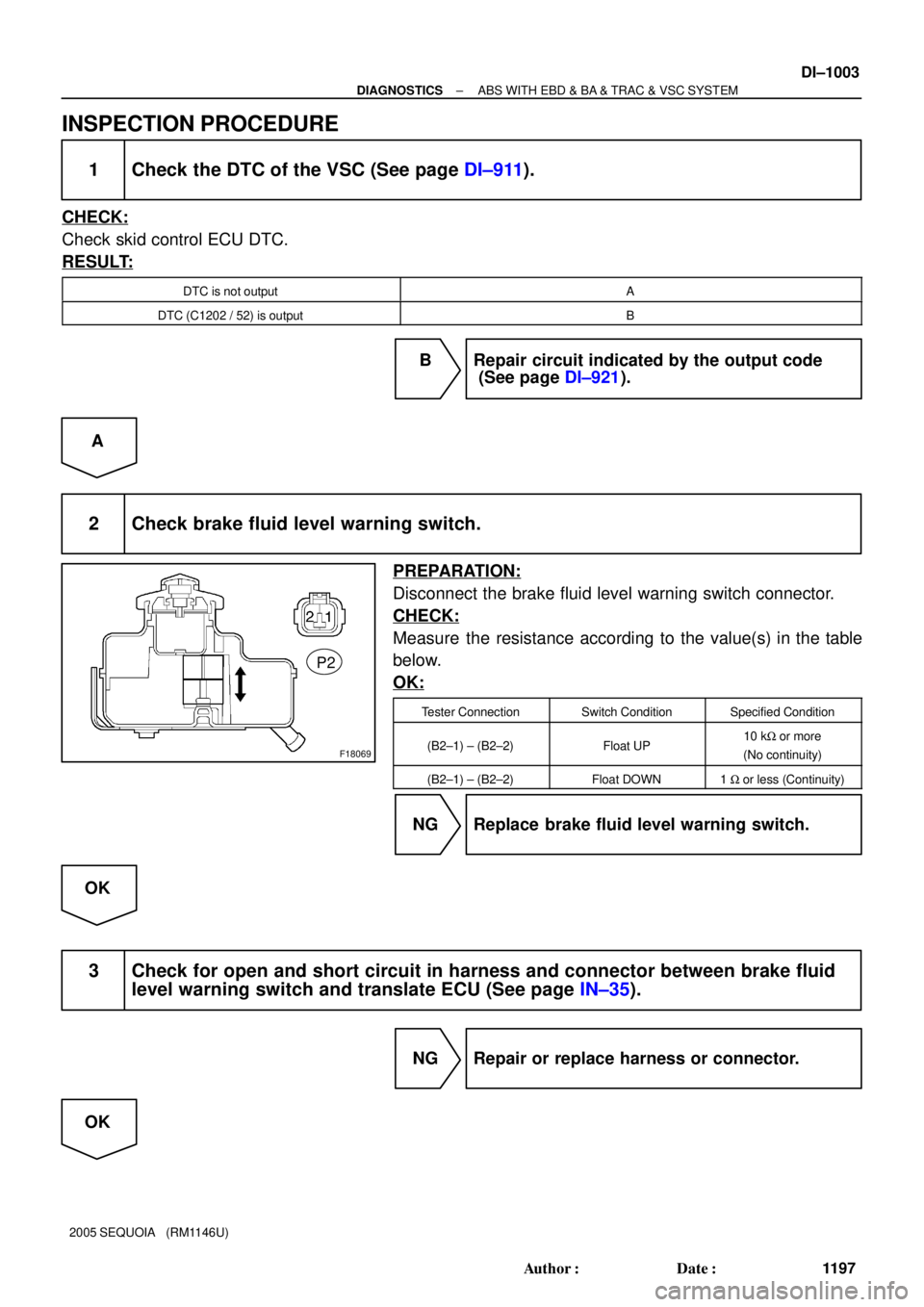
INSPECTION PROCEDURE
1 Check the DTC of the VSC (See page DI±911).
CHECK:
Check skid control ECU DTC.
RESULT:
DTC is not outputA
DTC (C1202 / 52) is outputB
B Repair circuit indicated by the output code
(See page DI±921).
A
2 Check brake fluid level warning switch.
PREPARATION:
Disconnect the brake fluid level warning switch connector.
CHECK:
Measure the resistance according to the value(s) in the table
below.
OK:
Tester ConnectionSwitch ConditionSpecified Condition
(B2±1) ± (B2±2)Float UP10 kW or more
(No continuity)
(B2±1) ± (B2±2)Float DOWN1 W or less (Continuity)
NG Replace brake fluid level warning switch.
OK
3 Check for open and short circuit in harness and connector between brake fluid
level warning switch and translate ECU (See page IN±35).
NG Repair or replace harness or connector.
OK
Page 1215 of 4323

DTC Normal Code Malfunction in Translate ECU
CIRCUIT DESCRIPTION
If any trouble occurs in the")
± DIAGNOSTICSABS WITH EBD & BA & TRAC & VSC SYSTEM
DI±1013
1207 Author�: Date�:
2005 SEQUOIA (RM1146U)
DTC Normal Code Malfunction in Translate ECU
CIRCUIT DESCRIPTION
If any trouble occurs in the engine control system, the skid control ECU prohibits ABS & VSC control.
DTC No.DTC Detecting ConditionTrouble Area
Normal Code
Conditions 1., 2. or 3. continue for 5 sec. or more:
1. Engine malfunction signal is sent from ECM.
2. Shift malfunction signal is sent from ECM.
3. The shift position is other than P and N, and P range
input voltage is 8 V or more.
�ECM circuit
�ECM
�Brake fluid level
�Brake fluid level warning switch circuit
�Steering angle sensor
�Translate ECU
�Skid control ECU
�Vehicle CAN
�VSC+, VSC± circuit (CAN1 communication system)
INSPECTION PROCEDURE
1 Is DTC output for ECM?
Check DTC on page DI±43.
YES Repair engine control system according to the
output code (See page DI±58).
NO
2 Check the DTC of the ABS and VSC (See page DI±911).
CHECK:
Check skid control ECU DTC.
RESULT:
Only DTC ºC1203/53º of the VSC system is outputA
Except DTC ºC1203/53º of the VSC system are outputB
B Repair ABS and VSC control system according
to the code output (See page DI±921).
A
DI6OF±12
Page 1217 of 4323
± DIAGNOSTICSABS WITH EBD & BA & TRAC & VSC SYSTEM
DI±1015
1209 Author�: Date�:
2005 SEQUOIA (RM1146U)
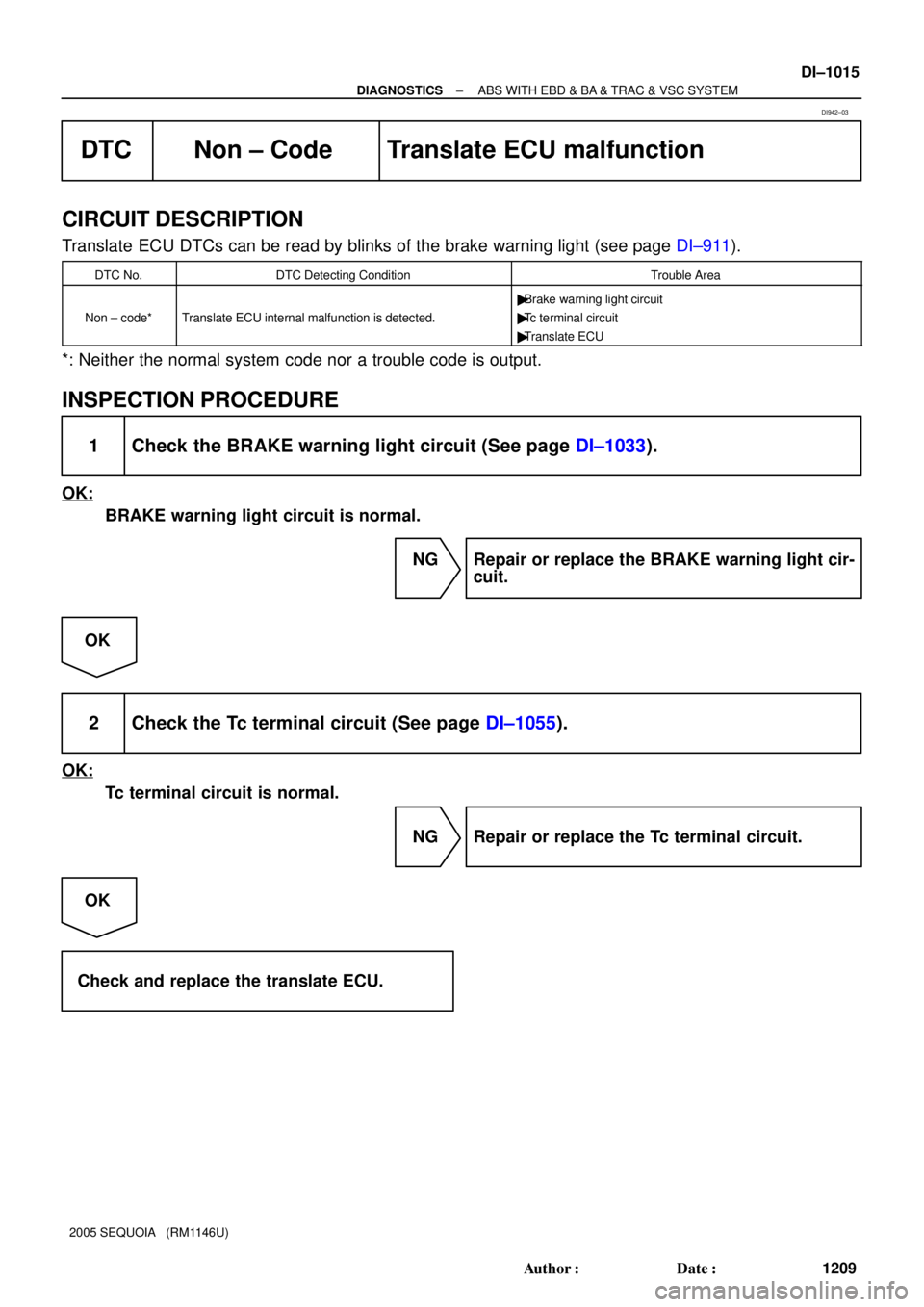
DTC Non ± Code Translate ECU malfunction
CIRCUIT DESCRIPTION
Translate ECU DTCs can be read by blinks of the brake warning light (see page DI±911).
DTC No.DTC Detecting ConditionTrouble Area
Non ± code*Translate ECU internal malfunction is detected.
�Brake warning light circuit
�Tc terminal circuit
�Translate ECU
*: Neither the normal system code nor a trouble code is output.
INSPECTION PROCEDURE
1 Check the BRAKE warning light circuit (See page DI±1033).
OK:
BRAKE warning light circuit is normal.
NG Repair or replace the BRAKE warning light cir-
cuit.
OK
2 Check the Tc terminal circuit (See page DI±1055).
OK:
Tc terminal circuit is normal.
NG Repair or replace the Tc terminal circuit.
OK
Check and replace the translate ECU.
DI942±03
Page 1235 of 4323
± DIAGNOSTICSABS WITH EBD & BA & TRAC & VSC SYSTEM
DI±1033
1227 Author�: Date�:
2005 SEQUOIA (RM1146U)
BRAKE Warning Light Circuit (Remains ON)
CIRCUIT DESCRIPTION
The BRAKE warning light comes on when the brake fluid is insufficient, the parking brake is applied or the
EBD is defective.
The skid control ECU is connected to the translate ECU via the CAN1 communication system.
DIDMN±01
Page 1236 of 4323
F19769
Translate ECU
VSC+
VSC±
IG17
T5
T511
1
T5B±RL
W
AA
J37
J38
A
J37B±R J/C
B±R B±RL
W 7
IL2
6
IL2
1
IL16
S1
2
S1
13
S1 ABS &VSC Actuator
(Skid Control ECU)
CANH
CANL
IG1
8
3C8
3A
B±R Instrument Panel J/B
4
1C
2
1C
3
1C
6
1C4
1F
11
1H
7
1J
1
1L ECU±IG
IGN1
AM1 B±R B±Y
W±R
W±LB±O
W±R
W
1 2Combination Meter
24
C6
Brake
1C5 W
8
ALTF10 Fusible
Link BlockEngine Room J/B
A W±R 1
2D1
2C
4
5
R±B R±B
B1 Brake Fluid Level
Warning SW
Y±L Y±LW±B 23
IA1
129
IA5O
A
A O
OJ43
J/C
IG Sub J/B No.4
LG±R
LG±R 4
4B4
4D
1P2 Parking
Brake SW
B
Battery 39
T5
24
T5
40
T5
4
T5 BRL
LVL2
GND
PKB2Sub J/B No.3
I18
Ignition SW
AM1 IG1
AM2 IG2 1
5 W±L
2
6
AM2
BB±R (*) CAN1 Circuit
(*)
(*)
(*) (*) DI±1034
± DIAGNOSTICSABS WITH EBD & BA & TRAC & VSC SYSTEM
1228 Author�: Date�:
2005 SEQUOIA (RM1146U)
WIRING DIAGRAM
Page 1237 of 4323

INSPECTION PROCEDURE
HINT:
Start the inspection f")
F18068
Parking Brake Switch
Release Push
P2
± DIAGNOSTICSABS WITH EBD & BA & TRAC & VSC SYSTEM
DI±1035
1229 Author�: Date�:
2005 SEQUOIA (RM1146U)
INSPECTION PROCEDURE
HINT:
Start the inspection from step 1 when using the hand±held tester and start from step 2 when not using the
hand±held tester.
1 Check operation of the BRAKE warning light.
PREPARATION:
(a) Connect the hand±held tester to the DLC3.
(b) Turn the ignition switch to the ON position and hand±held tester main switch ON.
(c) Select the ACTIVE TEST mode on the hand±held.
CHECK:
Check that ºONº and ºOFFº of the BRAKE warning light can be shown on the combination meter with the
hand±held tester.
ItemVehicle Condition/Test DetailsDiagnostic Note
BRAKE WARN LIGHTTurn BRAKE warning light ON/OFFObserve combination meter
OK:
BRAKE warning light operates.
NG Go to step 6.
OK
2 Check parking brake switch assembly.
PREPARATION:
Disconnect the parking brake switch connector.
CHECK:
Measure the resistance according to the value(s) in the table
below.
OK:
Tester ConnectionSwitch ConditionSpecified Condition
P2±1 ± Ground partReleased1 W or less
P2±1 ± Ground partPushed in10 kW or more
NG Replace parking brake switch.
OK


CANH
CANL
IG1
8
3C8
3A
B±R Instrum")