Page 3107 of 4323
SA24C±02
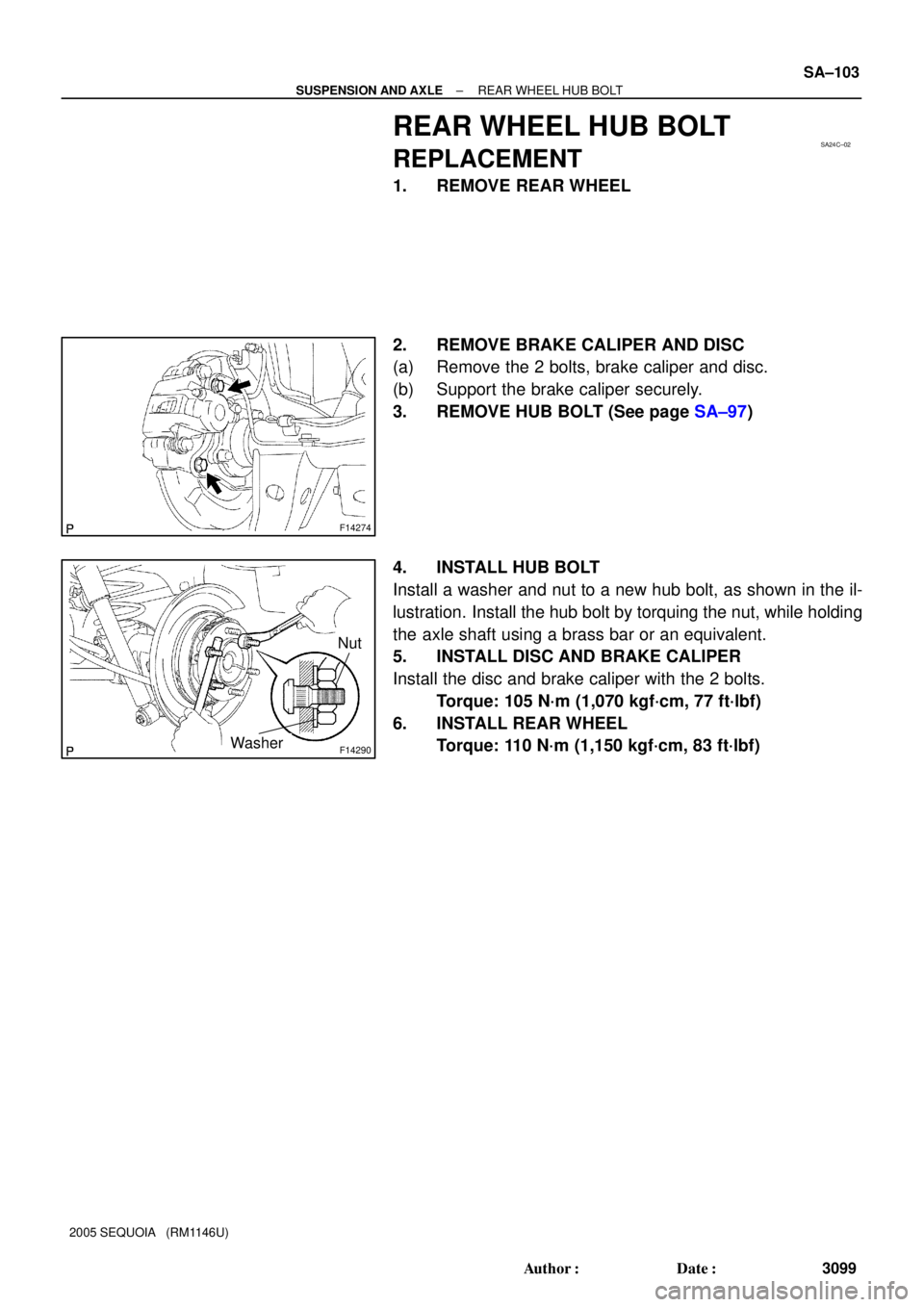
F14274
F14290
Nut
Washer
± SUSPENSION AND AXLEREAR WHEEL HUB BOLT
SA±103
3099 Author�: Date�:
2005 SEQUOIA (RM1146U)
REAR WHEEL HUB BOLT
REPLACEMENT
1. REMOVE REAR WHEEL
2. REMOVE BRAKE CALIPER AND DISC
(a) Remove the 2 bolts, brake caliper and disc.
(b) Support the brake caliper securely.
3. REMOVE HUB BOLT (See page SA±97)
4. INSTALL HUB BOLT
Install a washer and nut to a new hub bolt, as shown in the il-
lustration. Install the hub bolt by torquing the nut, while holding
the axle shaft using a brass bar or an equivalent.
5. INSTALL DISC AND BRAKE CALIPER
Install the disc and brake caliper with the 2 bolts.
Torque: 105 N´m (1,070 kgf´cm, 77 ft´lbf)
6. INSTALL REAR WHEEL
Torque: 110 N´m (1,150 kgf´cm, 83 ft´lbf)
Page 3113 of 4323
SA15M±05
F14291
Brake Caliper
Disc Parking Brake Assembly Drain Plug
�Gasket Filler Plug
Parking Brake
Cable Differential Carrier Axle Shaft (RH)
x10 Propeller ShaftAxle Shaft (LH)
Gasket �
�
49 (500, 36)
Clip
O±ring
�
122 (1,244, 90)
Gasket �
�49 (500, 36)
15.5 (158, 11)
N´m (kgf´cm, ft´lbf) : Specified torque
�Non±reusable part
74 (750, 55)
73 (744, 53)
105 (1,070, 77)
8.0 (82, 71 in.´lbf)10 (102, 7.4)
2WD:
74 (750, 55)
Stud Bolt
± SUSPENSION AND AXLEREAR DIFFERENTIAL CARRIER
SA±109
3105 Author�: Date�:
2005 SEQUOIA (RM1146U)
REAR DIFFERENTIAL CARRIER
COMPONENTS
Page 3115 of 4323

REMOVAL
1. REMOVE 2 REAR WHEELS
Torque: 110 N´m (1,122 kgf´cm")
SA24E±02
F14273
SST
F14274
F14276
± SUSPENSION AND AXLEREAR DIFFERENTIAL CARRIER
SA±111
3107 Author�: Date�:
2005 SEQUOIA (RM1146U)
REMOVAL
1. REMOVE 2 REAR WHEELS
Torque: 110 N´m (1,122 kgf´cm, 81 ft´lbf)
2. DRAIN HYPOID GEAR OIL
Torque: 49 N´m (500 kgf´cm, 36 ft´lbf)
3. DISCONNECT BRAKE LINES
(a) Using SST, disconnect the brake line and remove the clip.
SST 09023±00100
Torque: 15.5 N´m (158 kgf´cm, 11 ft´lbf)
(b) Use the same procedure described above to the other
side.
4. REMOVE BRAKE CALIPER AND DISC
(a) Remove the 2 bolts, brake caliper and disc.
Torque: 105 N´m (1,070 kgf´cm, 77 ft´lbf)
(b) Use the same procedure described above to the other
side.
5. REMOVE PARKING BRAKE ASSEMBLY
(a) Remove the parking brake assembly (See page
BR±43).
(b) Remove the 2 bolts and pull out the parking brake cable
from the backing plate.
Torque: 8.0 N´m (82 kgf´cm, 71 in.´lbf)
(c) Use the same procedures described above to the other
side.
6. REMOVE AXLE SHAFTS
(a) Remove the 4 nuts.
Torque: 122 N´m (1,244 kgf´cm, 90 ft´lbf)
(b) Pull out the axle shaft and remove the O±ring.
NOTICE:
Be careful not to damage the oil seal.
(c) Use the same procedures described above to the other
side.
Page 3142 of 4323

(c) While holding the piston rod, remove the nut, retainer,")
F16919
F16920
F14307
F04396
SA±138
± SUSPENSION AND AXLECOIL SPRING AND REAR SHOCK ABSORBER
3134 Author�: Date�:
2005 SEQUOIA (RM1146U)
(c) While holding the piston rod, remove the nut, retainer,
cushion and shock absorber.
Torque: 58 N´m (591 kgf´cm, 43 ft´lbf)
(d) Remove the retainer and cushion from the shock absorb-
er.
5. DISCONNECT LH AND RH STABILIZER BAR LINKS
Remove the 2 nuts and disconnect the LH and RH stabilizer bar
links.
Torque: 69 N´m (704 kgf´cm, 51 ft´lbf)
6. DISCONNECT LATERAL CONTROL ROD
Remove the nut, washer, bolt and disconnect the lateral control
rod.
Torque: 140 N´m (1,428 kgf´cm, 103 ft´lbf)
HINT:
At the time of installation, after stabilizing the suspension,
torque the nut and bolt.
7. REMOVE COIL SPRING
(a) Lower the axle housing.
NOTICE:
Be careful not to snap the brake line and parking brake
cable.
(b) While lowering the axle housing, remove the coil spring,
hollow spring and insulator.
HINT:
At the time of installation, please refer to the following items.
�Check that the coil spring end is installed correctly.
�If the coil spring end is not in the correct position, reinstall
the coil spring.
Page 3150 of 4323
SA17B±05
F14298
Speed Sensor
Wire Harness
Lower Control Arm
N´m (kgf´cm, ft´lbf) : Specified torque
Upper Control Arm
140 (1,428, 103)
140 (1,428, 103)
28 (286, 21)
130 (1,326, 96)
26 (265, 19)
Parking Brake Cable130 (1,326, 96)
Brake Line
Bracket
SA±146
± SUSPENSION AND AXLEREAR UPPER AND LOWER CONTROL ARM
3142 Author�: Date�:
2005 SEQUOIA (RM1146U)
REAR UPPER AND LOWER CONTROL ARM
COMPONENTS
Page 3151 of 4323
SA24J±02
F14299
F14300
± SUSPENSION AND AXLEREAR UPPER AND LOWER CONTROL ARM
SA±147
3143 Author�: Date�:
2005 SEQUOIA (RM1146U)
REMOVAL
1. REMOVE REAR WHEEL
Torque: 110 N´m (1,150 kgf´cm, 83 ft´lbf)
2. SUPPORT REAR AXLE HOUSING WITH JACK
3. REMOVE UPPER CONTROL ARM
(a) Disconnect the speed sensor wire harness.
(b) Remove the bolt and brake line bracket.
Torque: 28 N´m (286 kgf´cm, 21 ft´lbf)
(c) Remove the 2 nuts, washers, bolts and upper control arm.
Torque: 140 N´m (1,428 kgf´cm, 103 ft´lbf)
HINT:
At the time of installation, after stabilizing the suspension,
torque the nuts.
4. REMOVE LOWER CONTROL ARM
(a) Remove the bolt and parking brake cable bracket.
Torque: 26 N´m (265 kgf´cm, 19 ft´lbf)
(b) Remove the 2 nuts, bolts and lower control arm.
Torque: 130 N´m (1,326 kgf´cm, 96 ft´lbf)
HINT:
At the time of installation, after stabilizing the suspension,
torque the nuts.
Page 3160 of 4323

ADJUSTMENT
1. ADJUST STANDARD VEHICLE HEIGHT
(a) Releas")
SA2D0±01
F16824
HIGH
NORMAL
LOW SA±156
± SUSPENSION AND AXLEELECTRONIC MODULATED AIR SUSPENSION
3152 Author�: Date�:
2005 SEQUOIA (RM1146U)
ADJUSTMENT
1. ADJUST STANDARD VEHICLE HEIGHT
(a) Release the parking brake and stabilize the suspensions by pushing up and down on the corners of
the vehicle.
(b) Place the shift lever into the ºNº position and settle the tires by moving the vehicle back and forth.
(c) Start the engine.
(d) On the height control switch, first press ºHIGHº to raise the vehicle height, and then change the switch
to ºLOWº to lower it. Perform this operation one more time.
NOTICE:
Make sure to release the parking brake and move the shift lever into the ºNº position.
2. INSPECT TIRE (See page SA±3)
3. MEASURE VEHICLE HEIGHT (See page SA±4)
4. OPERATE HEIGHT CONTROL SWITCH AND CHECK
VEHICLE HEIGHT CHANGE
(a) Start the engine and change the height control switch
from the NORMAL position to the HIGH and LOW posi-
tions.
Check the time until the height adjustment is completed
and the amount of change in vehicle height.
Adjustment time
From operation of height control switch
to start of compressor.Approx. 2 sec.
From start of compressor to completion
of height adjustment.Approx. 20 sec.
Amount of change in vehicle height
HIGH position: 40 mm (1.57 in.)
LOW position:
4WD models: ±30 mm (±1.18 in.)
2WD models: ±15 mm (±0.59 in.)
Page 3176 of 4323
BR0A9±04
± BRAKEBRAKE SYSTEM
BR±1
3168 Author�: Date�:
2005 SEQUOIA (RM1146U)
BRAKE SYSTEM
PRECAUTION
�Care must be taken to replace each part properly as it could affect the performance of the brake
system and result in a driving hazard. Replace the parts with parts having the same part number
or equivalent.
�It is very important to keep parts and the area clean when repairing the brake system.
�If the vehicle is equipped with a mobile communication system, refer to the precautions in the
IN section.
 : Specified torque
Upper Control Arm
140 (1,428, 103)
140 (1,428, 103)
28 (286, 21)
130 (1,326, 96)
26 (265, 19)
Pa")