Page 2827 of 4323
CO0IQ±10
D12721
Intake Air
Connector PS Air
Hose
No.2 Fan ShroudThrottle Body Cover
Fan Pulley
Drive Belt Fan with Fluid Coupling
A/C Compressor
A/C Compressor
Connector
Engine Under Cover (4WD) x 5Radiator Assembly
N´m (kgf´cm, ft´lbf): Specified torque
12 (120, 9)
49 (500, 36)
A/T Oil Cooler Hose
Clip
Clip
Engine Under Cover (2WD) Vacuum Hose
PCV Hose
Suction Hose
MAF Meter Wire
± COOLINGWATER PUMP
CO±3
2819 Author�: Date�:
2005 SEQUOIA (RM1146U)
WATER PUMP
COMPONENTS
Page 2828 of 4323
B17476
RH No.3 Timing Belt Cover
LH No.3 Timing Belt CoverNo.2 Timing Belt Cover
Camshaft Position
Sensor Connector
Engine Wire
Oil Cooler Pipe
Timing Belt
Fan Bracket Drive Belt Timing Pulley
Timing Belt Tensioner Dust Boot
N´m (kgf´cm, ft´lbf) : Specified torque Cover Plate
39 (400,29)
32 (330, 24)
16 (160, 12)
Water Bypass
Hose
Grommet
16 (160, 12)
245 (2,500, 181)
CO±4
± COOLINGWATER PUMP
2820 Author�: Date�:
2005 SEQUOIA (RM1146U)
Page 2830 of 4323
CO0IR±06
B17478
B17479
CO±6
± COOLINGWATER PUMP
2822 Author�: Date�:
2005 SEQUOIA (RM1146U)
REMOVAL
1. DRAIN ENGINE COOLANT
2. REMOVE TIMING BELT (See page EM±16)
3. REMOVE NO.2 IDLER PULLEY (See page EM±16)
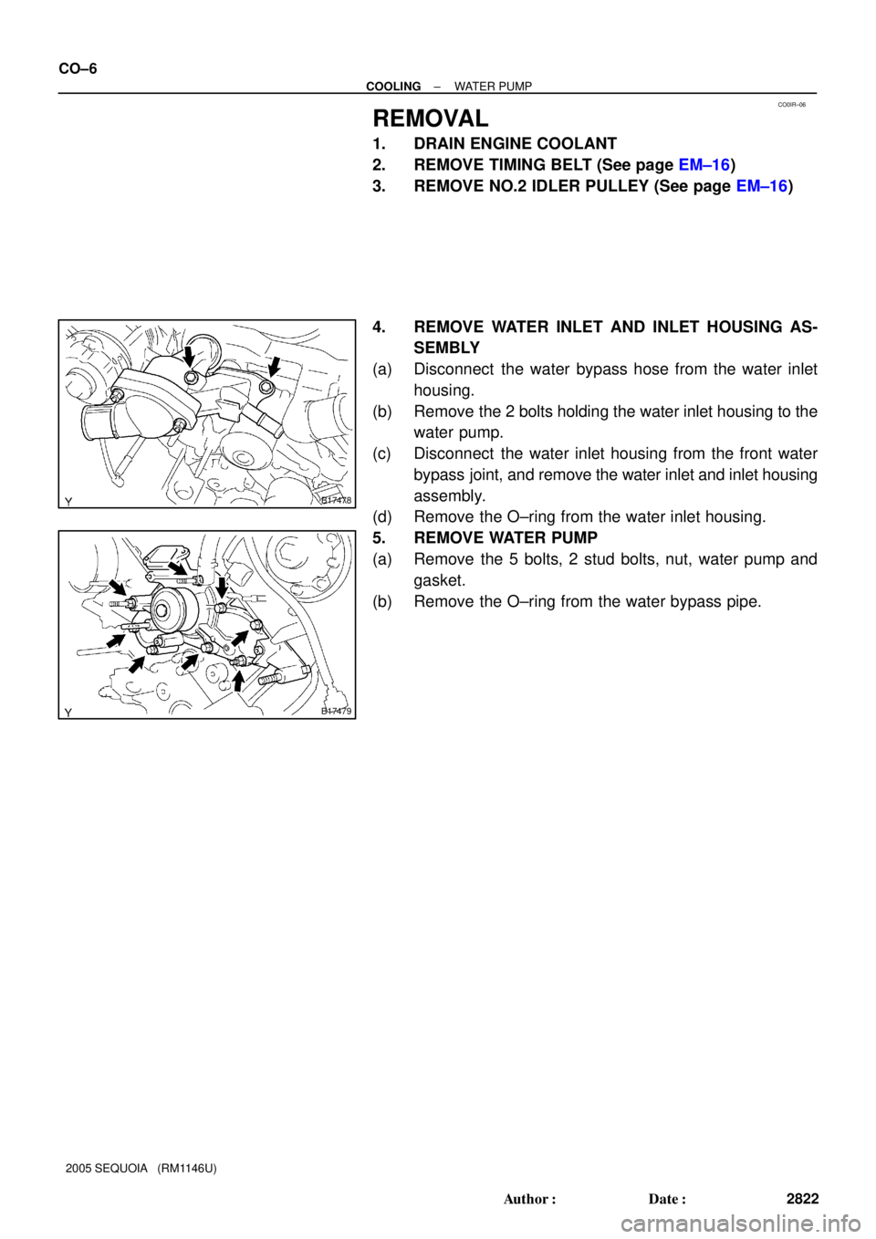
4. REMOVE WATER INLET AND INLET HOUSING AS-
SEMBLY
(a) Disconnect the water bypass hose from the water inlet
housing.
(b) Remove the 2 bolts holding the water inlet housing to the
water pump.
(c) Disconnect the water inlet housing from the front water
bypass joint, and remove the water inlet and inlet housing
assembly.
(d) Remove the O±ring from the water inlet housing.
5. REMOVE WATER PUMP
(a) Remove the 5 bolts, 2 stud bolts, nut, water pump and
gasket.
(b) Remove the O±ring from the water bypass pipe.
Page 2833 of 4323
B17478
AB
± COOLINGWATER PUMP
CO±9
2825 Author�: Date�:
2005 SEQUOIA (RM1146U)
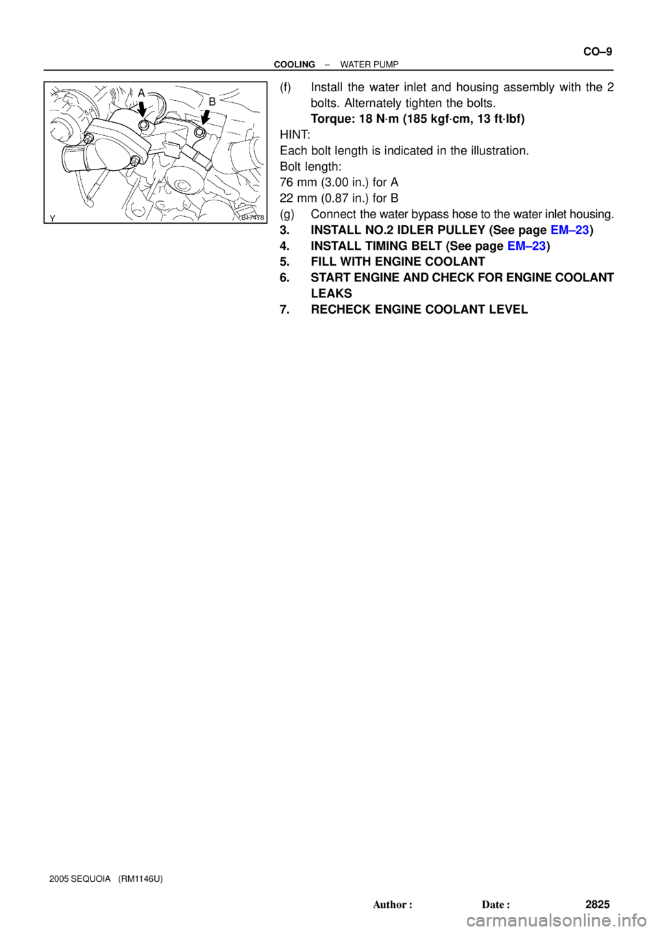
(f) Install the water inlet and housing assembly with the 2
bolts. Alternately tighten the bolts.
Torque: 18 N´m (185 kgf´cm, 13 ft´lbf)
HINT:
Each bolt length is indicated in the illustration.
Bolt length:
76 mm (3.00 in.) for A
22 mm (0.87 in.) for B
(g) Connect the water bypass hose to the water inlet housing.
3. INSTALL NO.2 IDLER PULLEY (See page EM±23)
4. INSTALL TIMING BELT (See page EM±23)
5. FILL WITH ENGINE COOLANT
6. START ENGINE AND CHECK FOR ENGINE COOLANT
LEAKS
7. RECHECK ENGINE COOLANT LEVEL
Page 2835 of 4323
CO0IV±04
B05866
± COOLINGTHERMOSTAT
CO±11
2827 Author�: Date�:
2005 SEQUOIA (RM1146U)
REMOVAL
HINT:
Removal of the thermostat would have an adverse effect, caus-
ing a lowering of cooling efficiency. Do not remove the thermo-
stat, even if the engine tends to overheat.
1. DRAIN ENGINE COOLANT
2. DISCONNECT WATER INLET FROM WATER INLET
HOUSING
Remove the 3 nuts and disconnect the water inlet from the wa-
ter inlet housing.
3. REMOVE THERMOSTAT
(a) Remove the thermostat.
(b) Remove the gasket from the thermostat.
Page 2837 of 4323
CO0IX±05
B07218
Jiggle Valve30°30°
± COOLINGTHERMOSTAT
CO±13
2829 Author�: Date�:
2005 SEQUOIA (RM1146U)
INSTALLATION
1. PLACE THERMOSTAT IN WATER INLET HOUSING
(a) Install a new gasket to the thermostat.
(b) Insert the thermostat into the water inlet housing with the
jiggle valve facing straight upward.
HINT:
The jiggle valve may be set within 30° of either side of the pre-
scribed position.
2. INSTALL WATER INLET
Install the water inlet with the 3 nuts.
Torque: 19 N´m (195 kgf´cm, 14 ft´lbf)
3. FILL WITH ENGINE COOLANT
4. START ENGINE AND CHECK FOR COOLANT LEAKS
5. RECHECK ENGINE COOLANT LEVEL
Page 2839 of 4323

ON±VEHICLE INSPECTION
1. REMOVE RADIA")
CO0IZ±08
CO1242
Radiator Cap Tester
Radiator Cap
30° or More
B07240
Radiator Cap Tester
± COOLINGRADIATOR
CO±15
2831 Author�: Date�:
2005 SEQUOIA (RM1146U)
ON±VEHICLE INSPECTION
1. REMOVE RADIATOR CAP
CAUTION:
To avoid the danger of being burned, do not remove the ra-
diator cap while the engine and radiator are still hot, as fluid
and steam can be blown out under pressure.
2. INSPECT RADIATOR CAP
NOTICE:
�If the radiator cap has contaminations, always rinse
it with water.
�Before using a radiator cap tester, wet the relief valve
and pressure valve with engine coolant or water.
�When performing steps (a) and (b) below, keep the
tester at an angle of over 30° above the horizontal.
(a) Using a radiator cap tester, slowly pump the tester and
check that air is coming from the vacuum valve.
Pump speed: 1 push/(3 seconds or more)
NOTICE:
Push the pump at a constant speed.
If air is not coming from the vacuum valve, replace the radiator
cap.
(b) Pump the radiator cap tester, and measure the relief valve
opening pressure.
Pump speed: 1 push within 1 second
NOTICE:
This pump speed is for the first pump only (in order to close
the vacuum valve). After this, the pump speed can be re-
duced.
Opening pressure:
Standard74 to 103 kPa (0.75 to 1.05 kgf/cm2,10.7 to 14.9 psi)
Minimum59 kPa (0.6 kgf/cm2, 8.6 psi)
HINT:
Use the tester's maximum reading as the opening pressure.
If the opening pressure is less than minimum, replace the radia-
tor cap.
3. INSPECT COOLING SYSTEM FOR LEAKS
(a) Fill the radiator with coolant and attach a radiator cap tes-
ter.
(b) Warm up the engine.
(c) Pump it to 118 kPa (1.2 kgf/cm
2, 17.1 psi), and check that
the pressure does not drop.
If the pressure drops, check the hoses, radiator or water pump
for leaks. If no external leaks are found, check the heater core,
cylinder block and head.
4. REINSTALL RADIATOR CAP
Page 2840 of 4323
CO1D2±01
B07246
Radiator Assembly
A/T Oil Cooler Hose
Engine Under Cover (4WD)Upper Radiator Hose
Lower Radiator Hose
x 5
N´m (kgf´cm, ft´lbf) : Specified torque
12 (120, 9)
No.1 Fan Shroud
No.2 Fan Shroud
Engine Under Cover (2WD)
Clip
Clip
CO±16
± COOLINGRADIATOR
2832 Author�: Date�:
2005 SEQUOIA (RM1146U)
COMPONENTS
 x 5")


Upper Radiator Hose
Lower Radiator Hose
x 5
N´m (kgf´cm, ft´lbf) : Specified torque
12 (120, 9)
No.1 Fan Shroud
No.2 F")