Page 2785 of 4323
B17469
SF0P7±16
B17470
± SFITHROTTLE BODY
SF±43
2777 Author�: Date�:
2005 SEQUOIA (RM1146U)
INSTALLATION
1. INSTALL THROTTLE BODY
(a) Install the throttle body with the nut and 3 bolts.
Torque: 14 N´m (143 kgf´cm, 10 ft´lbf)
(b) Connect the 2 water bypass hoses to the throttle body.
(c) Connect the throttle control connector.
2. INSTALL INTAKE AIR CONNECTOR
3. FILL WITH ENGINE COOLANT (See page CO±2)
4. START ENGINE AND CHECK FOR ENGINE COOLANT
LEAKS
5. INSTALL THROTTLE BODY COVER
Page 2791 of 4323
SF0PD±04
B17508
B17509
Disconnect
± SFIACOUSTIC CONTROL INDUCTION SYSTEM (ACIS)
SF±49
2783 Author�: Date�:
2005 SEQUOIA (RM1146U)
ACOUSTIC CONTROL INDUCTION
SYSTEM (ACIS)
ON±VEHICLE INSPECTION
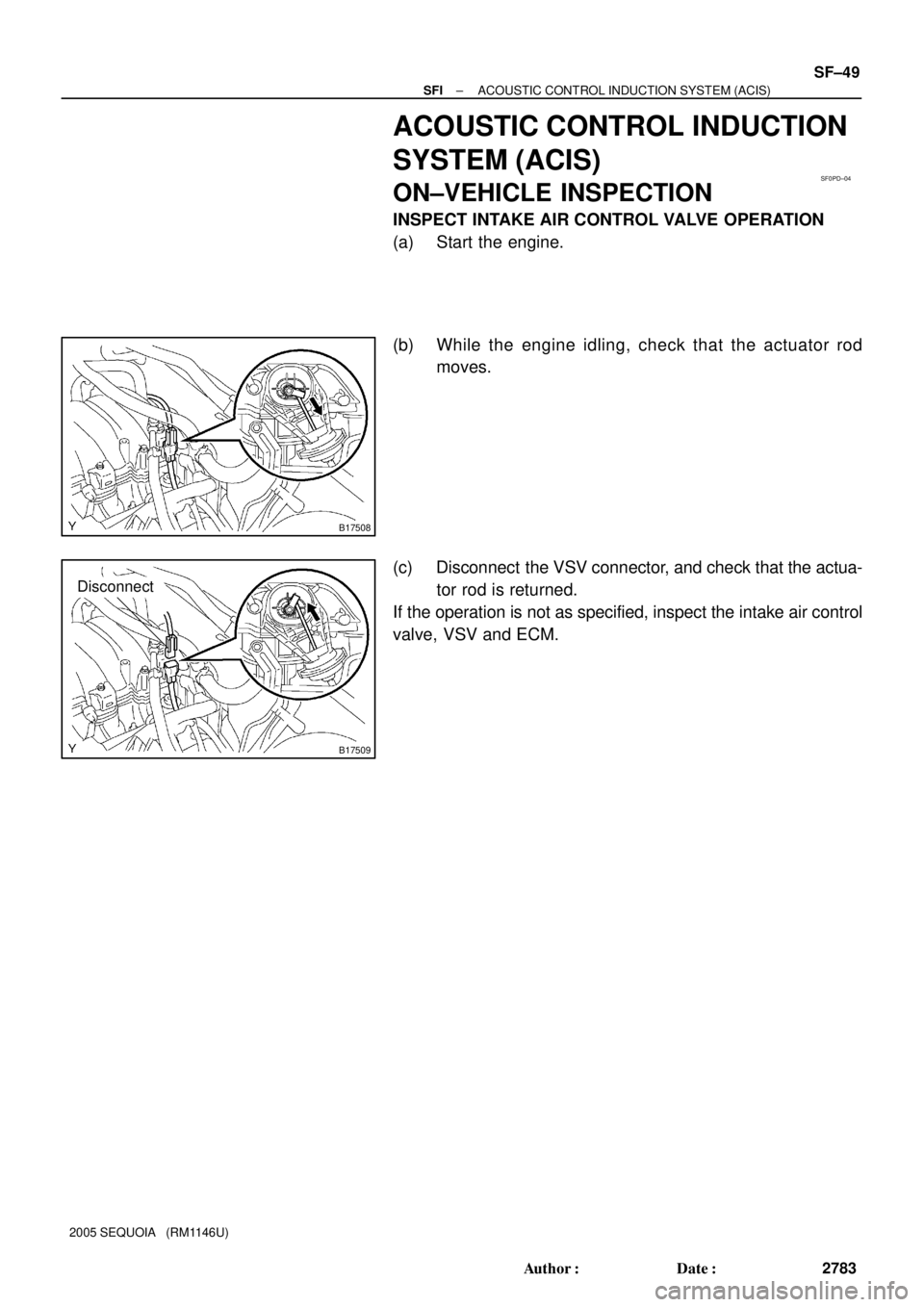
INSPECT INTAKE AIR CONTROL VALVE OPERATION
(a) Start the engine.
(b) While the engine idling, check that the actuator rod
moves.
(c) Disconnect the VSV connector, and check that the actua-
tor rod is returned.
If the operation is not as specified, inspect the intake air control
valve, VSV and ECM.
Page 2793 of 4323
B17490
N´m (kgf´cm, ft´lbf) : Specified torque
�Gasket
Non±reusable part�
18 (185, 13)
VSV Connector for
EVAP Injector Connector
Fuel Return Hose VSV ConnectorEngine Wire
Engine Wire
Throttle Body
Connector
18 (185, 13)
Injector Connector VSV Connector
18 (185, 13)
Engine Wire
± SFIACOUSTIC CONTROL INDUCTION SYSTEM (ACIS)
SF±51
2785 Author�: Date�:
2005 SEQUOIA (RM1146U)
Page 2806 of 4323
SF0PN±14
B17471
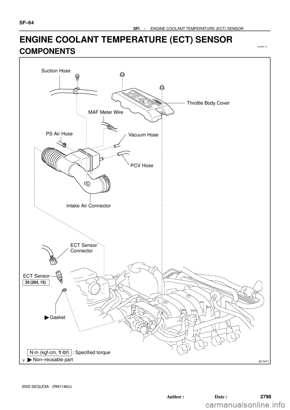
PS Air Hose
PCV Hose
Intake Air Connector
� GasketECT Sensor
Connector
ECT Sensor
N´m (kgf´cm, ft´lbf) : Specified torque
� Non±reusable part
Vacuum HoseThrottle Body Cover
MAF Meter Wire
Suction Hose
20 (204, 15)
SF±64
± SFIENGINE COOLANT TEMPERATURE (ECT) SENSOR
2798 Author�: Date�:
2005 SEQUOIA (RM1146U)
ENGINE COOLANT TEMPERATURE (ECT) SENSOR
COMPONENTS
Page 2807 of 4323
 Acceptable 30
20
10
5
3
2
1
0.5
0.3
0.2
0.1
40 ±20 0 20 60 80 100
(212) (176) (140) (104) (68) (32) (±4)
± SFIENGINE")
SF0PO±19
B02308
S01196S01699Z17274
Ohmmeter
Resistance kW
Temperature °C (°F) Acceptable 30
20
10
5
3
2
1
0.5
0.3
0.2
0.1
40 ±20 0 20 60 80 100
(212) (176) (140) (104) (68) (32) (±4)
± SFIENGINE COOLANT TEMPERATURE (ECT) SENSOR
SF±65
2799 Author�: Date�:
2005 SEQUOIA (RM1146U)
INSPECTION
1. DRAIN ENGINE COOLANT
2. REMOVE THROTTLE BODY COVER
3. REMOVE INTAKE AIR CONNECTOR
4. DISCONNECT THROTTLE BODY FROM INTAKE MAN-
IFOLDS
Remove the nut and 3 bolts, and disconnect the throttle body
from the intake manifold.
5. REMOVE ECT SENSOR
(a) Disconnect the ECT sensor connector.
(b) Remove the ECT sensor and gasket.
6. INSPECT ECT SENSOR
Using an ohmmeter, measure the resistance between the ter-
minals.
Resistance: Refer to the graph
If the resistance is not as specified, replace the ECT sensor.
7. REINSTALL ECT SENSOR
(a) Install a new gasket and the ECT sensor.
Torque: 19.6 N´m (200 kgf´cm, 14 ft´lbf)
(b) Connect the ECT sensor connector.
8. REINSTALL THROTTLE BODY TO INTAKE MAN-
IFOLDS
Install a new gasket and the throttle body with the 2 bolts and
2 nuts.
Torque: 20 N´m (204 kgf´cm, 15 ft´lbf)
9. REINSTALL INTAKE AIR CONNECTOR
10. REFILL WITH ENGINE COOLANT (See page CO±2)
11. REINSTALL THROTTLE BODY COVER
Page 2809 of 4323
B17473
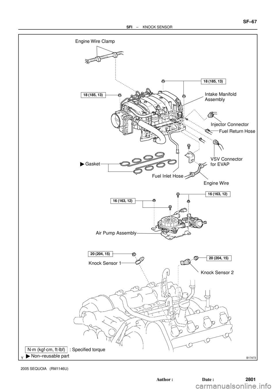
Engine Wire Clamp
Injector Connector
� Gasket
18 (185, 13)
N´m (kgf´cm, ft´lbf): Specified torque
� Non±reusable part
18 (185, 13)
Knock Sensor 2
VSV Connector
for EVAP
Fuel Inlet Hose
Knock Sensor 1Fuel Return Hose
Intake Manifold
Assembly
Engine Wire
20 (204, 15)20 (204, 15)
Air Pump Assembly
16 (163, 12)
16 (163, 12)
± SFIKNOCK SENSOR
SF±67
2801 Author�: Date�:
2005 SEQUOIA (RM1146U)
Page 2810 of 4323
SF1XU±01
B17474
B17475
B17503
Engine
Rear
Engine
RearUpper
Upper
0° ± 10°0° ± 10° SF±68
± SFIKNOCK SENSOR
2802 Author�: Date�:
2005 SEQUOIA (RM1146U)
INSPECTION
1. REMOVE THROTTLE BODY COVER
2. REMOVE INTAKE AIR CONNECTOR
3. REMOVE INTAKE MANIFOLDS ASSEMBLY
(See page EM±36)
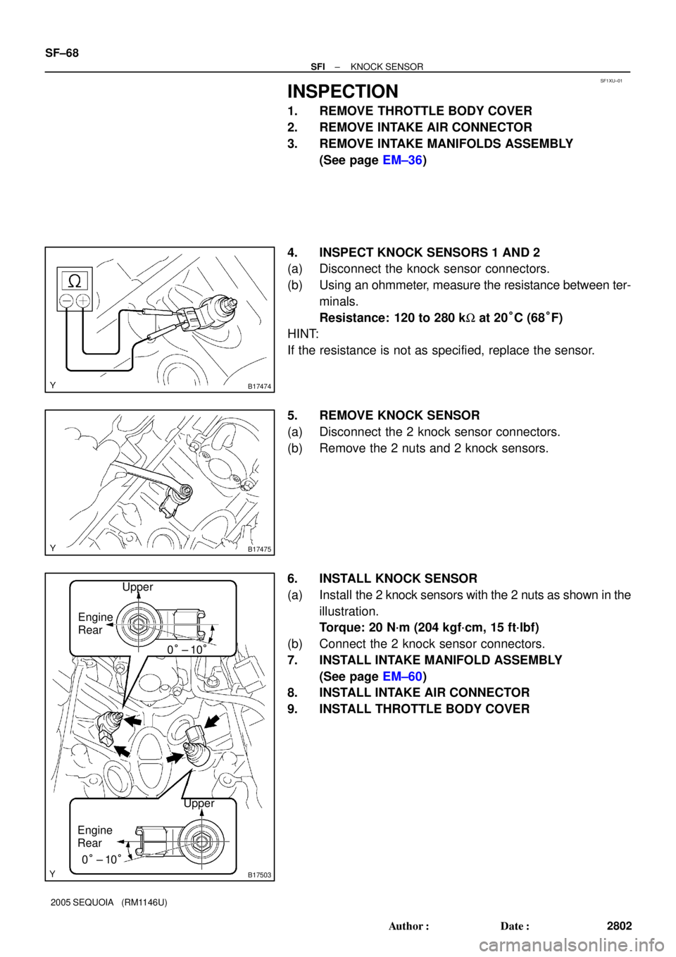
4. INSPECT KNOCK SENSORS 1 AND 2
(a) Disconnect the knock sensor connectors.
(b) Using an ohmmeter, measure the resistance between ter-
minals.
Resistance: 120 to 280 kW at 20°C (68°F)
HINT:
If the resistance is not as specified, replace the sensor.
5. REMOVE KNOCK SENSOR
(a) Disconnect the 2 knock sensor connectors.
(b) Remove the 2 nuts and 2 knock sensors.
6. INSTALL KNOCK SENSOR
(a) Install the 2 knock sensors with the 2 nuts as shown in the
illustration.
Torque: 20 N´m (204 kgf´cm, 15 ft´lbf)
(b) Connect the 2 knock sensor connectors.
7. INSTALL INTAKE MANIFOLD ASSEMBLY
(See page EM±60)
8. INSTALL INTAKE AIR CONNECTOR
9. INSTALL THROTTLE BODY COVER
Page 2811 of 4323
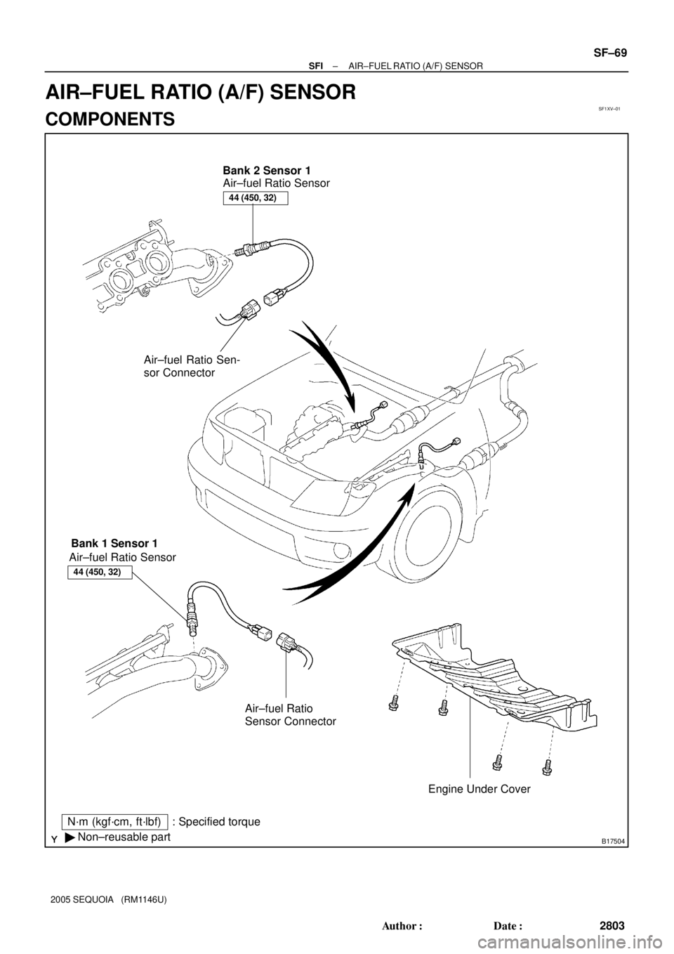
SF1XV±01
B17504
N´m (kgf´cm, ft´lbf)
� Non±reusable part: Specified torqueAir±fuel Ratio Sensor
Engine Under Cover Bank 2 Sensor 1
Bank 1 Sensor 1
Air±fuel Ratio
Sensor Connector Air±fuel Ratio Sensor
44 (450, 32)
Air±fuel Ratio Sen-
sor Connector
44 (450, 32)
± SFIAIR±FUEL RATIO (A/F) SENSOR
SF±69
2803 Author�: Date�:
2005 SEQUOIA (RM1146U)
AIR±FUEL RATIO (A/F) SENSOR
COMPONENTS