Page 2711 of 4323

14. INSTALL REAR OIL SEAL RETAINER
(")
A04848
Seal Width
3 ± 4 mm A
BA
B
A04855
New O±Ring
P12477
Seal Packing EM±124
± ENGINE MECHANICALCYLINDER BLOCK
2703 Author�: Date�:
2005 SEQUOIA (RM1146U)
14. INSTALL REAR OIL SEAL RETAINER
(a) Remove any old packing (FIPG) material and be careful
not to drop any oil on the contacting surfaces of the oil
seal retainer and cylinder block.
�Using a razor blade and gasket scraper, remove all
the old packing (FIPG) materials from the gasket
surfaces and sealing grooves.
�Thoroughly clean all components to remove all the
loose material.
�Using a non±residue solvent, clean both sealing
surfaces.
(b) Apply seal packing to the oil seal retainer as shown in the
illustration.
Seal packing: Part No. 08826±00080 or equivalent
�Install a nozzle that has been cut to a 3 ± 4 mm (0.12
± 0.16 in.) opening.
�Parts must be assembled within 5 minutes of ap-
plication. Otherwise the material must be removed
and reapplied.
�Immediately remove nozzle from the tube and rein-
stall cap.
(c) Install a new O±ring to the cylinder block.
(d) Install the oil seal retainer with the 7 bolts.
Torque: 8.0 N´m (80 kgf´cm, 71 in.´lbf)
15. INSTALL ENGINE COOLANT DRAIN UNIONS
(a) Apply seal packing to 2 or 3 threads.
Seal packing: Part No. 08826±00100 or equivalent
Page 2712 of 4323

(b) Install the 2 drain unions.
Torque: 49 N")
A04856
FrontPort
A08472
LH Side
A05132
Push
Wire
Clamp
New
O±Ring
± ENGINE MECHANICALCYLINDER BLOCK
EM±125
2704 Author�: Date�:
2005 SEQUOIA (RM1146U)
(b) Install the 2 drain unions.
Torque: 49 N´m (500 kgf´cm, 36 ft´lbf)
HINT:
After applying the specified torque, rotate the drain union clock-
wise until its drain port is facing forward.
16. INSTALL OIL PUMP (See page LU±15)
17. INSTALL OIL STRAINER (See page LU±15)
18. INSTALL NO.1 OIL PAN (See page LU±15)
19. INSTALL OIL PAN BAFFLE PLATE
(See page LU±15)
20. INSTALL NO.2 OIL PAN (See page LU±15)
21. INSTALL WATER PUMP (See page CO±8)
22. INSTALL ENGINE MOUNTING BRACKETS
Install the mounting bracket with the 4 bolts. Install the 2 mount-
ing brackets.
Torque: 36 N´m (370 kgf´cm, 27 ft´lbf)
23. INSTALL ENGINE WIRE TO LH SIDE OF CYLINDER
BLOCK
(a) Install the brackets on the engine wire with the 2 bolts.
(b) Install the engine wire cover with the 2 bolts.
24. INSTALL OIL COOLER PIPE BRACKET FOR A/T
Install the bracket with the bolt.
25. INSTALL VVT SENSORS (See page SF±77)
26. INSTALL KNOCK SENSORS (See page SF±66)
27. INSTALL STARTER (See page ST±16)
28. INSTALL WATER BYPASS PIPE
(a) Install a new O±ring to the water bypass pipe.
(b) Apply soapy water to the O±ring.
(c) Push in the water bypass pipe end into the pipe hole of
the water pump.
(d) Install the water bypass pipe with the bolt.
Torque: 18 N´m (185 kgf´cm, 13 ft´lbf)
(e) Install the wire clamp to the bracket of the water bypass
pipe.
29. INSTALL CYLINDER HEADS (See page EM±60)
30. INSTALL TIMING BELT AND PULLEYS
(See page EM±23)
31. DISCONNECT ENGINE FROM ENGINE STAND
Page 2713 of 4323
EM0EE±20
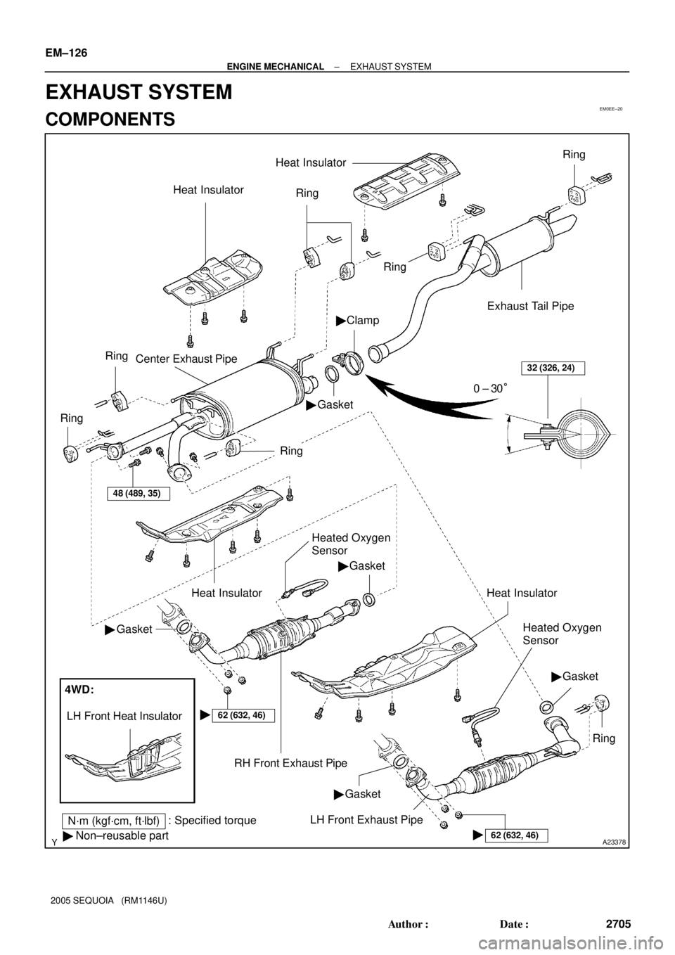
A23378
N´m (kgf´cm, ft´lbf): Specified torque
� Non±reusable partHeat Insulator
�
Ring
Ring
Clamp
Gasket Center Exhaust Pipe
Ring
Ring
�
Exhaust Tail Pipe
Ring
Heat Insulator
32 (326, 24)
0 ± 30°
Ring
48 (489, 35)
Heat Insulator
�Gasket
�Gasket
RH Front Exhaust Pipe
62 (632, 46)�
4WD:
LH Front Heat Insulator
Heated Oxygen
Sensor
Heat Insulator
Heated Oxygen
Sensor
�Gasket
Ring
62 (632, 46)�
LH Front Exhaust Pipe�Gasket
EM±126
± ENGINE MECHANICALEXHAUST SYSTEM
2705 Author�: Date�:
2005 SEQUOIA (RM1146U)
EXHAUST SYSTEM
COMPONENTS
Page 2714 of 4323
EM1X4±01
A23379
A23380
A23381
A23382
A23383
± ENGINE MECHANICALEXHAUST SYSTEM
EM±127
2706 Author�: Date�:
2005 SEQUOIA (RM1146U)
REMOVAL
1. REMOVE HEATED OXYGEN SENSORS
(a) Disconnect the heated oxygen sensor.
(b) Remove the heated oxygen sensor.
2. REMOVE RH AND LH FRONT EXHAUST PIPES
(a) Remove the 6 nuts and 2 gaskets, and disconnect the
front exhaust pipes from the exhaust manifold.
(b) Remove the 4 bolts, 2 gaskets and 2 front exhaust pipes
from the center exhaust pipe.
3. REMOVE CENTER EXHAUST PIPE
(a) Loosen the clamp bolt, disconnect the center exhaust
pipe and remove the gasket from the exhaust tail pipe.
(b) Remove the 5 rings and center exhaust pipe.
4. REMOVE EXHAUST TAIL PIPE
Remove the 2 rings and exhaust tail pipe.
5. REMOVE HEAT INSULATOR
(a) Remove the 5 bolts and No.1 heat insulator.
(b) Remove the 4 bolts and No.2 heat insulator.
(c) Remove the 3 bolts and No.3 heat insulator.
(d) Remove the 2 bolts and No.4 heat insulator.
Page 2715 of 4323

INSTALLATION
1. INSTALL HEAT INSULATOR
(a) Install the No.1 heat insulato")
EM1X5±01
A23383
A23382
A23380
A23381
EM±128
± ENGINE MECHANICALEXHAUST SYSTEM
2707 Author�: Date�:
2005 SEQUOIA (RM1146U)
INSTALLATION
1. INSTALL HEAT INSULATOR
(a) Install the No.1 heat insulator with the 5 bolts.
(b) Install the No.2 heat insulator with the 4 bolts.
(c) Install the No.3 heat insulator with the 3 bolts.
(d) Install the No.4 heat insulator with the 2 bolts.
2. INSTALL EXHAUST TAIL PIPE
(a) Install the 2 rings and exhaust tail pipe.
3. INSTALL CENTER EXHAUST PIPE
(a) Install the 5 rings and center exhaust pipe.
(b) Install a new gasket and connect the center exhaust pipe
to the exhaust tail pipe with a new clamp.
Torque: 32 N´m (326 kgf´cm, 24 ft´lbf)
4. INSTALL RH AND LH FRONT EXHAUST PIPES
(a) Install 2 new gaskets and connect the 2 front exhaust
pipes with the 6 nuts to the exhaust manifold.
Torque: 62 N´m (632 kgf´cm, 46 ft´lbf)
(b) Install 2 new gaskets and connect the 2 front exhaust pipe
with the 4 bolts to the center exhaust pipe.
Torque: 48 N´m (489 kgf´cm, 35 ft´lbf)
Page 2716 of 4323
A23379
± ENGINE MECHANICALEXHAUST SYSTEM
EM±129
2708 Author�: Date�:
2005 SEQUOIA (RM1146U)
5. INSTALL HEATED OXYGEN SENSORS
(a) Install the heated oxygen sensor.
Torque: 44 N´m (450 kgf´cm, 33 ft´lbf)
(b) Connect the heated oxygen sensor connector.
Page 2717 of 4323
EC087±03
± EMISSION CONTROLEMISSION CONTROL SYSTEM
EC±1
2709 Author�: Date�:
2005 SEQUOIA (RM1146U)
EMISSION CONTROL SYSTEM
PURPOSE
The emission control systems are installed to reduce the amount of HC, CO and NOx exhausted from the
engine ((3) and (4)), to prevent the atmospheric release of blow±by gas±containing HC (1) and evaporated
fuel containing HC being released from the fuel tank (2).
The function of each system is shown in these table:
SystemAbbreviationFunction
(1) Positive Crankcase Ventilation
(2) Evaporative Emission Control
(3) Three±Way Catalytic Converter
(4) Sequential Multiport Fuel Injection*PCV
EVAP
TWC
SFIReduces HC
Reduces evaporated HC
Reduces HC, CO and NOx
Injects a precisely timed, optimum amount of fuel for reduced exhaust
emissions
Remark: * For inspection and repair of the SFI system, refer to the SF section in this manual.
Page 2725 of 4323
 CONTROL SYSTEM
EC±9
2717 Author�: Date�:
2005 SEQUOIA (RM1146U)
INSP")
EC0JL±03
B17594
Gasket
B06544
Vacuum Gauge
D13872
Hand±Held Tester
DLC3
CAN VIM
± EMISSION CONTROLEVAPORATIVE EMISSION (EVAP) CONTROL SYSTEM
EC±9
2717 Author�: Date�:
2005 SEQUOIA (RM1146U)
INSPECTION
1. INSPECT LINES AND CONNECTIONS
Visually check for loose connections, sharp bends or damage.
2. INSPECT FUEL TANK
Visually check for deformation, cracks or fuel leakage.
3. INSPECT FUEL TANK CAP
Visually check if the cap and/or gasket are deformed or dam-
aged.
If necessary, repair or replace the cap.
4. INSPECT EVAP SYSTEM LINE
(a) Warm up the engine to normal operating temperature and
stop the engine.
(b) Install a vacuum gauge (EVAP control system test equip-
ment vacuum gauge) into the EVAP service port on the
purge line.
(c) When using a hand±held tester:
Operation of the VSV for EVAP.
(1) Connect a hand±held tester to the Controller Area
Network Vehicle Interface Module (CAN VIM). Then
connect the CAN VIM to the Date Link Connector 3
(DLC3).
(2) Start the engine.
(3) Turn the hand±held tester ON.
(4) Enter the following menus: DIAGNOSIS / EN-
HANCED OBDII/ ACTIVE TEST / EVAP VAV
(ALONE)