Page 2749 of 4323

Front
Fuel
Pipe
Gasket SST
(Union)SST
(Adaptor)
± SFIFUEL PUMP
SF±7
2741 Author�: Date�:
2005 SEQUO")
D13872
Hand±Held Tester
DLC3
CAN VIM
SF12Y±05
B16497
Up
Pulsation
DamperScrew
B16528
SST
(Gauge)
Front
Fuel
Pipe
Gasket SST
(Union)SST
(Adaptor)
± SFIFUEL PUMP
SF±7
2741 Author�: Date�:
2005 SEQUOIA (RM1146U)
FUEL PUMP
ON±VEHICLE INSPECTION
1. CHECK FUEL PUMP OPERATION
(a) Connect a hand±held tester to the Controller Area Net-
work Vehicle Interface Module (CAN VIM). Then connect
the CAN VIM to the Date Link Connector 3 (DLC3).
(b) Turn the ignition switch ON, and push the hand±held tes-
ter main switch ON.
NOTICE:
Do not start the engine.
(c) Enter the following menus: DIAGNOSIS / ENHANCED
OBDII / ACTIVE TEST / FUEL PUMP / SPD
(d) Please refer to the hand±held tester operator's manual
for further details.
(e) Check that the pulsation damper screw rises when the
fuel pump operates.
If operation is not as specified, check the fusible link, fuses, EFI
main relay, fuel pump, ECM and wiring connections.
(f) Turn the ignition switch off.
(g) Disconnect the hand±held tester and CAN VIM from the
DLC3.
2. CHECK FUEL PRESSURE
(a) Check the battery positive voltage is 12 V or more.
(b) Disconnect the negative (±) terminal cable from the bat-
tery.
(c) Remove the front fuel pipe from the LH delivery pipe. (See
page SF±27)
(d) Install the front fuel pipe and SST (pressure gauge) to the
delivery pipe with the 3 lower gaskets and SST (adaptor).
SST 09268±45014 (09268±41190, 90405±06167)
Torque: 39 N´m (400 kgf´cm, 29 ft´lbf)
(e) Wipe off any splattered gasoline.
(f) Reconnect the negative (±) terminal cable to the battery.
(g) Connect a hand±held tester to the DLC3. (See step 1 in
check fuel pump operation (a) to (e))
Page 2750 of 4323

(h) Measure the fuel pressure.
Fuel pressure:
265 to 304 kPa (2.7 to 3.1 kgf/cm
2, 38 to 44 psi)
If pressure is high, replace the fu")
SF±8
± SFIFUEL PUMP
2742 Author�: Date�:
2005 SEQUOIA (RM1146U)
(h) Measure the fuel pressure.
Fuel pressure:
265 to 304 kPa (2.7 to 3.1 kgf/cm
2, 38 to 44 psi)
If pressure is high, replace the fuel pressure regulator.
If pressure is low, check the fuel hoses and connections, fuel
pump, fuel filter and fuel pressure regulator.
(i) Disconnect the hand±held tester and CAN VIM from the
DLC3.
(j) Start the engine.
(k) Measure the fuel pressure at idle.
Fuel pressure:
265 to 304 kPa (2.7 to 3.1 kgf/cm
2, 38 to 44 psi)
(l) Stop the engine.
(m) Check that the fuel pressure remains as specified for 5
minutes after the engine has stopped.
Fuel pressure: 147 kPa (1.5 kgf/cm
2, 21 psi) or more
If pressure is not as specified, check the fuel pump, pressure
regulator and/or injectors.
(n) After checking fuel pressure, disconnect the negative (±)
terminal cable from the battery and carefully remove the
SST to prevent gasoline from splashing.
SST 09268±45014
(o) Reinstall the front fuel pipe to the LH delivery pipe. (See
page SF±31)
3. CONNECT CABLE TO NEGATIVE BATTERY TERMI-
NAL
4. PERFORM INITIALIZATION (See page IN±20)
Some systems need initialization when disconnecting the cable
from the negative battery terminal.
5. CHECK FOR FUEL LEAKS (See page SF±1)
Page 2768 of 4323
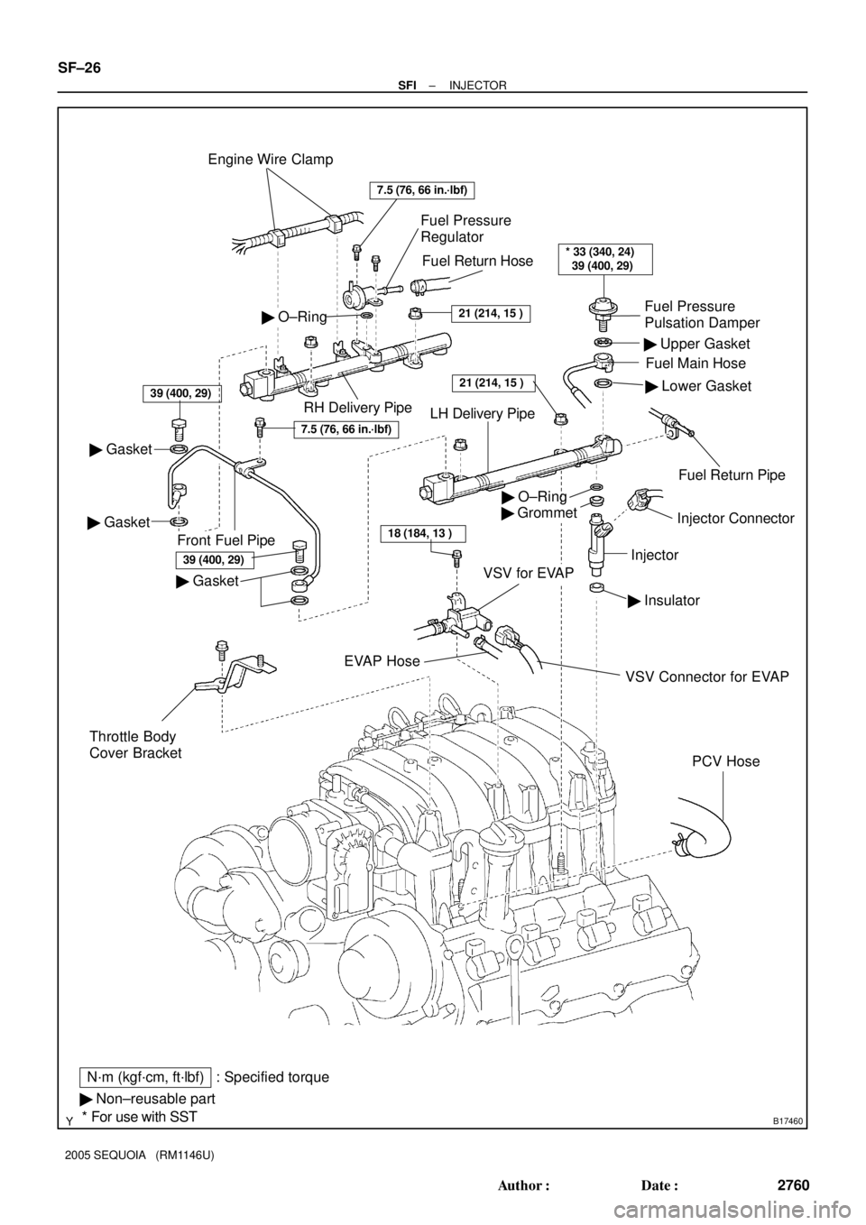
B17460
Engine Wire Clamp
Fuel Pressure
Regulator
� Gasket� Upper Gasket
� Lower Gasket
RH Delivery Pipe
Front Fuel Pipe
� Grommet
Injector
� Insulator
Fuel Main Hose
VSV for EVAPFuel Pressure
Pulsation Damper
� Gasket
� O±Ring
Injector Connector
PCV Hose
N´m (kgf´cm, ft´lbf)
� Non±reusable part: Specified torque
* For use with SST
� Gasket
39 (400, 29)
39 (400, 29)
Fuel Return Pipe
� O±Ring
Fuel Return Hose
Throttle Body
Cover Bracket
VSV Connector for EVAP
EVAP Hose
21 (214, 15 )
21 (214, 15 )
LH Delivery Pipe
7.5 (76, 66 in.´lbf)
18 (184, 13 )
* 33 (340, 24)
39 (400, 29)
7.5 (76, 66 in.´lbf)
SF±26
± SFIINJECTOR
2760 Author�: Date�:
2005 SEQUOIA (RM1146U)
Page 2769 of 4323

(b)
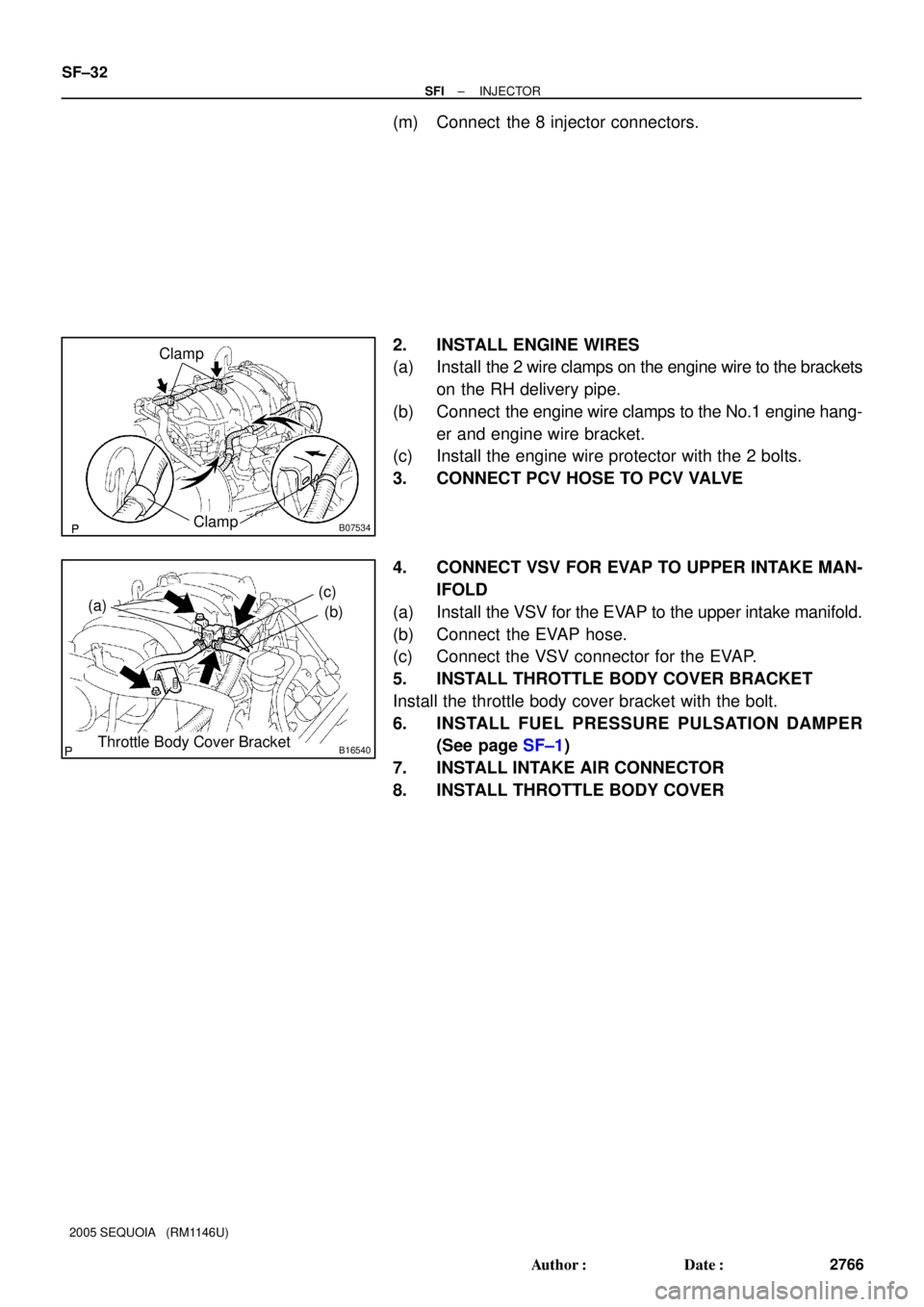
Throttle Body Cover Bracket
(c)
B07045ClampClamp
Clamp
± SFIINJECTOR
SF±27
2761 Author�: Date�:
2005 SEQUOIA (RM1146U)
REMOVAL
1. DISCHARGE FUEL SYSTEM PRESSURE
(Se")
SF133±08
B07312
B16540
(a)
(b)
Throttle Body Cover Bracket
(c)
B07045ClampClamp
Clamp
± SFIINJECTOR
SF±27
2761 Author�: Date�:
2005 SEQUOIA (RM1146U)
REMOVAL
1. DISCHARGE FUEL SYSTEM PRESSURE
(See page SF±1)
2. REMOVE THROTTLE BODY COVER
3. REMOVE INTAKE AIR CONNECTOR
4. REMOVE FUEL PRESSURE PULSATION DAMPER
Remove the pulsation damper, upper gasket, fuel main hose
and lower gasket.
NOTICE:
�Put a shop rag under the delivery pipe.
�Slowly loosen the pulsation damper.
5. DISCONNECT PCV HOSE FROM PCV VALVE
6. DISCONNECT VSV FOR EVAP
(a) Disconnect the VSV connector for EVAP.
(b) Disconnect the EVAP hose.
(c) Remove the VSV for EVAP from the intake manifold.
7. REMOVE THROTTLE BODY COVER BRACKET
Remove the bolt and throttle body cover bracket.
8. DISCONNECT ENGINE WIRES
(a) Disconnect the engine wire clamps from the No.1 engine
hanger and engine wire bracket.
(b) Disconnect the 2 wire clamps on the engine wire from the
brackets on the RH delivery pipe.
9. REMOVE DELIVERY PIPES AND INJECTORS
NOTICE:
�Be careful not to drop the injectors when removing
the delivery pipes.
�Do not apply any load to the injector in horizontal
direction.
Page 2771 of 4323

SST (Union)
Fuel Return Hose
B00884
SST
(Adaptor)
SST
(Hose)
SST
(Clamp)
Vinyl
HoseO±Ring
D13872
Hand�")
SF134±04
B07326
SST
InjectorSST
SST
SST
Pressure Regulator
B04988
Pressure Regulator
SST (Hose)
SST (Union)
Fuel Return Hose
B00884
SST
(Adaptor)
SST
(Hose)
SST
(Clamp)
Vinyl
HoseO±Ring
D13872
Hand±Held Tester
DLC3
CAN VIM
± SFIINJECTOR
SF±29
2763 Author�: Date�:
2005 SEQUOIA (RM1146U)
INSPECTION
1. INSPECT INJECTOR INJECTION
CAUTION:
Keep the injector clean of sparks during the test.
(a) Disconnect the fuel inlet hose (fuel tube connector) from
the fuel filter.
(b) Connect SST (attachment and hose) to the fuel tube.
SST 09268±41047 (09268±52011)
(c) Remove the pressure regulator from the delivery pipe.
(d) Install the O±ring to the fuel inlet of the pressure regulator.
(e) Connect SST (hose) to the fuel inlet of the pressure regu-
lator with SST (union) and the 2 bolts.
SST 09268±41047 (09268±41091)
Torque: 7.5 N´m (76 kgf´cm, 66 in.´lbf)
(f) Connect the fuel return hose to the fuel outlet of the pres-
sure regulator.
(g) Install the O±ring to the injector.
(h) Connect SST (adaptor and hose) to the injector, and hold
the injector and union with SST (clamp).
SST 09268±41047 (09268±41110, 09268±41300)
(i) Put the injector into the graduated cylinder.
CAUTION:
Install a suitable vinyl hose onto the injector to prevent
gasoline from splashing out.
(j) Connect a hand±held tester to the Controller Area Net-
work Vehicle Interface Module (CAN VIM). Then connect
the CAN VIM to the Date Link Connector 3 (DLC3).
(k) Connect the battery negative (±) cable to the battery.
(l) Turn the ignition switch ON, and push the hand±held tes-
ter main switch ON.
NOTICE:
Do not start the engine.
(m) Enter the following menus: DIAGNOSIS / ENHANCED
OBDII / ACTIVE TEST / FUEL PUMP / SPD
(n) Please refer to the hand±held tester operator's manual
for further details.
Page 2774 of 4323
B07534
Clamp
Clamp
B16540
(a)(c)
(b)
Throttle Body Cover Bracket
SF±32
± SFIINJECTOR
2766 Author�: Date�:
2005 SEQUOIA (RM1146U)
(m) Connect the 8 injector connectors.
2. INSTALL ENGINE WIRES
(a) Install the 2 wire clamps on the engine wire to the brackets
on the RH delivery pipe.
(b) Connect the engine wire clamps to the No.1 engine hang-
er and engine wire bracket.
(c) Install the engine wire protector with the 2 bolts.
3. CONNECT PCV HOSE TO PCV VALVE
4. CONNECT VSV FOR EVAP TO UPPER INTAKE MAN-
IFOLD
(a) Install the VSV for the EVAP to the upper intake manifold.
(b) Connect the EVAP hose.
(c) Connect the VSV connector for the EVAP.
5. INSTALL THROTTLE BODY COVER BRACKET
Install the throttle body cover bracket with the bolt.
6. INSTALL FUEL PRESSURE PULSATION DAMPER
(See page SF±1)
7. INSTALL INTAKE AIR CONNECTOR
8. INSTALL THROTTLE BODY COVER
Page 2781 of 4323

THROTTLE BODY
ON±VEHICLE INSPECTION
1. REMOVE THROTTLE BODY COVER
2. IN")
B17467
SF1XJ±01
D13872
Hand±Held Tester
DLC3
CAN VIM
± SFITHROTTLE BODY
SF±39
2773 Author�: Date�:
2005 SEQUOIA (RM1146U)
THROTTLE BODY
ON±VEHICLE INSPECTION
1. REMOVE THROTTLE BODY COVER
2. INSPECT SYSTEM OPERATION
(a) Inspect the throttle control motor for operating sound.
(1) Turn the ignition switch ON.
(2) When depressing the accelerator pedal, check the
running sound of the motor. Also, check that there
is no friction sound.
If operation is not as specified, check the throttle control motor
(see step 3), wiring and ECM.
(b) Inspect the accelerator pedal position sensor.
(1) Connect a hand±held tester to the Controller Area
Network Vehicle Interface Module (CAN VIM). Then
connect the CAN VIM to the Date Link Connector 3
(DLC3).
(2) Check that the MIL does not light up.
(3) When turning the accelerator pedal position sensor
lever to the full±open position, check that the
throttle valve opening percentage (THROTTLE
POS) of the CURRENT DATA showns the standard
value.
Standard throttle valve opening percentage:
60% or more
If operation is not as specified, check that the accelerator pedal
position sensor (see page DI±370), wiring and ECM.
If not using a hand±held tester, measure the voltage between
terminals (VTA1±E2, VTA2±E2) of the ECM connector (See
page DI±127).
(c) Inspect the idle speed.
(1) Start the engine and check that the MIL does not
light up.
(2) Allow the engine to warm up to normal operating
temperature.
(3) Turn the A/C compressor ON to OFF, and check the
idle speed.
Idle speed (Transmission in neutral): 700 ± 50 rpm
NOTICE:
Perform inspection without an electrical load.
(d) After checking the above (a) to (c), perform the driving test
and check that there is no sense of incongruity.
Page 2784 of 4323
SF0P5±16
B17470
B17469
SF±42
± SFITHROTTLE BODY
2776 Author�: Date�:
2005 SEQUOIA (RM1146U)
REMOVAL
1. REMOVE THROTTLE BODY COVER
2. DRAIN ENGINE COOLANT
3. REMOVE INTAKE AIR CONNECTOR
4. REMOVE THROTTLE BODY
(a) Disconnect the throttle control connector.
(b) Disconnect the 2 water bypass hoses from the throttle
body.
(c) Remove the nut and 3 bolts, and remove the throttle body
from the intake manifold.