Page 2726 of 4323
 CONTROL SYSTEM
2718 Author�: Date�:
2005 SEQUOIA (RM1146U)
(d) When not using a hand±held tester:
Ope")
B16489
Battery
B06545
Vacuum Gauge
B17595
EC±10
± EMISSION CONTROLEVAPORATIVE EMISSION (EVAP) CONTROL SYSTEM
2718 Author�: Date�:
2005 SEQUOIA (RM1146U)
(d) When not using a hand±held tester:
Operation of the VSV for the EVAP.
(1) Disconnect the VSV for the EVAP connector.
(2) Connect leads from the positive (+) and negative (±)
battery terminals to the VSV for EVAP terminals.
(3) Start the engine.
(e) Check the vacuum when the engine idles.
Vacuum:
Maintain between 0.368 and 19.713 in.Hg (5 to 268
in.Aq) for over 5 seconds
HINT:
If the vacuum does not change, the hose connecting the VSV
and the service port is loose or blocked, or the VSV is malfunc-
tioning.
(f) When using a hand±held tester:
Conclude operation of the VSV for EVAP.
(1) Stop the engine.
(2) Disconnect the hand±held tester from the DLC3.
(g) When not using a hand±held tester:
Conclude operation of the VSV for EVAP.
(1) Stop the engine.
(2) Disconnect the positive (+) and negative (±) leads
of the battery from the VSV for EVAP terminals.
(3) Connect the VSV for EVAP connector.
(h) Disconnect the vacuum gauge from the EVAP service
port on the purge line.
(i) Connect a pressure gauge to the EVAP service port on
the purge line.
(j) Check the pressure.
(1) Prepare a rubber hose that has an inside diameter
of 15 to 18.5 mm.
(2) Disconnect the atmospheric side hose of the pump
module.
(3) Connect the prepared rubber hose to the pump
module, and pinch the rubber hose with the clip to
prevent air from entering into the canister passage.
Page 2736 of 4323
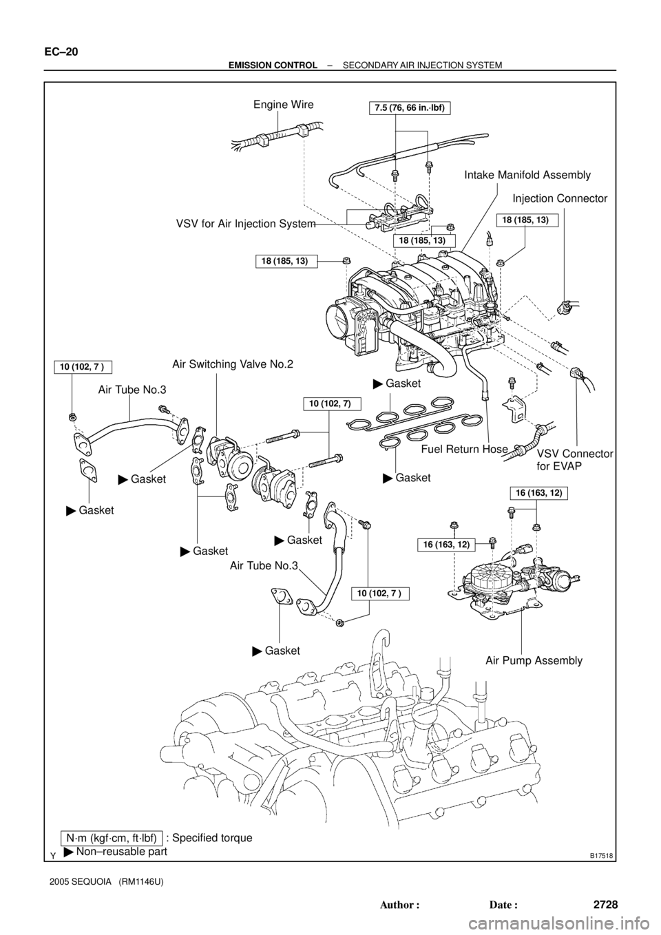
B17518
� Gasket
� Gasket Air Switching Valve No.2
Air Tube No.3
Air Tube No.3� GasketInjection Connector Engine Wire
VSV Connector
for EVAP Fuel Return Hose
N´m (kgf´cm, ft´lbf): Specified torque
� Non±reusable part
� Gasket
� Gasket
Air Pump Assembly
Intake Manifold Assembly
� Gasket
� Gasket
7.5 (76, 66 in.´lbf)
VSV for Air Injection System
18 (185, 13)
18 (185, 13)
18 (185, 13)
10 (102, 7 )
16 (163, 12)
16 (163, 12)
10 (102, 7 )
10 (102, 7)
EC±20
± EMISSION CONTROLSECONDARY AIR INJECTION SYSTEM
2728 Author�: Date�:
2005 SEQUOIA (RM1146U)
Page 2743 of 4323

SFI SYSTEM
PRECAUTION
HINT:
All DTCs retained in the ECM will be erased when the negative
(±) terminal cable is removed")
SF1XD±01
± SFISFI SYSTEM
SF±1
2735 Author�: Date�:
2005 SEQUOIA (RM1146U)
SFI SYSTEM
PRECAUTION
HINT:
All DTCs retained in the ECM will be erased when the negative
(±) terminal cable is removed from the battery.
If necessary, read the DTC before removing the negative (±)
terminal cable from the battery.
1. BEFORE WORKING ON FUEL SYSTEM,
DISCON-
NECT CABLE FROM NEGATIVE (±) BATTERY TERMI-
NAL
2. DO NOT SMOKE OR WORK NEAR AN OPEN FLAME
WHEN WORKING ON FUEL SYSTEM
3. KEEP GASOLINE AWAY FROM RUBBER OR
LEATH-
ER PARTS
4. MAINTENANCE PRECAUTIONS
(a) To prevent engine misfire, these precautions should be
taken.
(1) Check the battery terminals are proper connected.
(2) After repair, check that the ignition coil terminals
and all other ignition system lines are reconnected
securely.
(3) When cleaning the engine compartment, be espe-
cially careful to protect the electrical system from
water.
(b) Observe the following when handling the air fuel ratio
sensors and oxygen sensor.
(1) Do not drop the sensor or hit it against another ob-
ject.
(2) The sensor should be free from any contact with wa-
ter.
5. IF VEHICLE IS EQUIPPED WITH MOBILE RA-
DIO
SYSTEM (HAM, CB, ETC.)
If the vehicle is equipped with a mobile communication system,
refer to the precaution in the IN section.
6. AIR INDUCTION SYSTEM
(a) Removal of the engine oil dipstick, oil filler cap, PCV hose,
may break the engine.
(b) Disconnection, looseness or cracks in the parts of the air
induction system between the throttle body and cylinder
head may result in air suction and break the engine.
7. ELECTRONIC CONTROL SYSTEM
(a) Before removing SFI wiring connectors, terminals, first
disconnect the power by turning the ignition switch off or
disconnecting the negative (±) terminal cable from the
battery.
HINT:
Be sure to check DTCs before disconnecting the negative (±)
terminal cable from the battery.
Page 2744 of 4323

(b) When installing the battery, be especially careful to cor-
rectly connect the positive (+) and neg")
FI2553
SST
B16498
New Gasket
SF±2
± SFISFI SYSTEM
2736 Author�: Date�:
2005 SEQUOIA (RM1146U)
(b) When installing the battery, be especially careful to cor-
rectly connect the positive (+) and negative (±) cables.
(c) Do not give a severe impact to the SFI parts during remov-
al or installation. Handle all SFI parts carefully, especially
the ECM.
(d) Be careful during troubleshooting. Numerous transistor
circuits are used and even slight terminal contact can
cause further trouble.
(e) Do not open the ECM cover.
(f) When inspecting during rainy weather, take care to pre-
vent entry of water. Also, when washing the engine
compartment, prevent water from getting into the SFI
parts and wiring connectors.
(g) Parts should be replaced as an assembly.
(h) Care should be taken when pulling out and inserting wir-
ing connectors.
(1) Release the lock and pull out the connector, pulling
on the connectors.
(2) Fully insert the connector and check that it is locked.
(i) Use SST for inspection or test of the injector or its wiring
connector.
SST 09842±30070
8. FUEL SYSTEM
(a) When disconnecting the high fuel pressure line, a large
amount of gasoline will spill out. Observe the following
procedures:
(1) Disconnect the circuit opening relay.
(2) Start the engine. After the engine has stopped on
its own, turn the ignition switch off.
(3) Put a container under the connecting part of the
pressure line.
(4) Slowly loosen the connection.
(5) Disconnect the high fuel pressure line.
(6) Reconnect the fuel pump connector.
(b) When connecting the union bolt (fuel pressure pulsation
damper) on the high pressure pipe union, observe the fol-
lowing procedures:
(1) Always use 2 new gaskets.
(2) Tighten the union bolt by hand.
Page 2745 of 4323

B16499
Fulcrum
Length
30 cm
SST
B02714
CORRECT
WRONG
Delivery Pipe O±Ring
B04939
Delivery
Pipe
Intake
Manifold O±Ring
Grommet
Injector
Insulator
B17532
Quick Type
Disconnect
B11684
Quick Type
Push
Pull
± SFISFI SYSTEM
SF±3
2737 Author�: Date�:
2005 SEQUOIA (RM1146U)
(3) Using SST, tighten the union bolt to the specified
torque.
SST 09612±24014 (09617±24011)
Torque:
33 N´m (340 kgf´cm, 24 ft´lbf) for use with SST
39 N´m (400 kgf´cm, 29 ft´lbf)
HINT:
Use a torque wrench with a fulcrum length of 30 cm (11.81 in.).
(c) Observe the following precautions when removing or
installing the injectors.
(1) Never reuse the O±ring.
(2) When placing a new O±ring on the injector, take
care not to damage it in any way.
(3) Coat a new O±ring with spindle oil or gasoline be-
fore installing. Never use engine, gear or brake oil.
(d) Install the injector to the delivery pipe and intake manifold
as shown in the illustration.
Before installing the injector, apply spindle oil or gasoline
on the place where the delivery pipe or the intake man-
ifold touches the O±ring of the injector.
(e) Observe the following when disconnecting the fuel tube
connector (quick type):
(1) Check if there is any dirt in the pipe and around the
connector before disconnecting the fuel tube con-
nector. If necessary, clean the dirt away.
(2) Disconnect the fuel pipe clamp from the connector.
(3) Be sure to disconnect them by hand.
(4) When the connector and the pipe are stuck, push
and pull the connector. Then disconnect and pull it
out. Do not use any tools at this time.
(5) Check if there is any dirt or other foreign matter on
the seal surface of the disconnected pipe. If neces-
sary, clean the dirt away.
(6) Do not damage the disconnected pipe and connec-
tor and prevent intrusion of foreign objects by cover-
ing them with a plastic bag.
Page 2746 of 4323

B11683
Quick Type
Push
B12520
Quick Type
Pull
B17533
Quick Type
Install
B06584
Metallic Type
O±Ring Retainer Pipe
Nylon Tube
Housing
B09688
Metallic Type
SST
SF±4
± SFISFI SYSTEM
2738 Author�: Date�:
2005 SEQUOIA (RM1146U)
(f) Observe the following when connecting the fuel tube con-
nector (quick type):
(1) Check if there is any damage or foreign objects in
the connected part of the pipe.
(2) Match the axis of the connector with the axis of the
pipe, and push into the connector until a ºclickº
sound is heard. If the connection is tight, apply a
small amount of fresh engine oil on the tip of the
pipe.
(3) After finishing the connection, pull the pipe and the
connector to ensure it is secure.
(4) Check to make sure no fuel leak is present.
If the result is not specified, repair or replace.
(5) Install the fuel pipe clamp to the connector.
(6) Check to make sure no fuel leak is present.
If the result is not specified, repair or replace.
(g) Observe the following when disconnecting the fuel tube
connector (metallic type):
HINT:
The structure of the metallic connector is shown on the left.
(1) Check if there is any dirt in the pipe and around the
connector before disconnecting the fuel tube con-
nector. If necessary, clean the dirt away.
(2) Assemble SST to the connecting part, as shown in
the illustration.
SST 09268±21010
Page 2747 of 4323

B10036
Metallic Type
Pull Connector
B10485
Metallic Type
Push
B10485
Metallic Type
Pull
± SFISFI SYSTEM
SF±5
2739 Author�: Date�:
2005 SEQUOIA")
B10035
Metallic Type
SST
Insert Retainer
(at 4 places)
B10036
Metallic Type
Pull Connector
B10485
Metallic Type
Push
B10485
Metallic Type
Pull
± SFISFI SYSTEM
SF±5
2739 Author�: Date�:
2005 SEQUOIA (RM1146U)
(3) Turn the SST, align the retainers inside the connec-
tor with the SST chamfered parts and insert the SST
into the connector.
(4) While holding the SST, pull the connector towards
the SST to put the retainers on the SST chamfered
parts.
(5) Slide the SST and connector together towards the
fuel tube assembly.
(h) Observe the following when connecting the fuel tube con-
nector (metallic type):
(1) Check if there is any damage or foreign objects in
the connected part of the pipe.
(2) Match the axis of the connector with the axis of the
pipe, and push into the connector until a ºclickº
sound is heard. If the connection is tight, apply a
small amount of fresh engine oil on the tip of the
pipe.
(3) After finishing the connection, pull the pipe and the
connector to ensure it is secure.
(4) Check to make sure no fuel leak is present.
If the result is not specified, repair or replace.
(i) Observer the following when handling the nylon tube:
(1) Pay attention not to turn the connected part of the
nylon tube and the quick connector with tube when
connecting them.
(2) Pay attention not to kink the nylon tube.
(3) Do not remove the nylon tube.
(4) Do not close the piping with the nylon tube by bend-
ing it.
Page 2748 of 4323

(j) Check that there is any fuel leak after maintenance any-
wh")
D13872
Hand±Held Tester
DLC3
CAN VIM
B16500
Fuel Return Hose
Pinch
SF±6
± SFISFI SYSTEM
2740 Author�: Date�:
2005 SEQUOIA (RM1146U)
(j) Check that there is any fuel leak after maintenance any-
where on the fuel system.
(1) Connect a hand±held tester to the Controller Area
Network Vehicle Interface Module (CAN VIM). Then
connect the CAN VIM to the Date Link Connector 3
(DLC3).
(2) Turn the ignition switch ON and push the hand±held
tester main switch ON.
NOTICE:
Do not start the engine.
(3) Enter the following menus: DIAGNOSIS / EN-
HANCED OBDII / ACTIVE TEST / FUEL PUMP /
SPD.
(4) Please refer to the hand±held tester operator's
manual for further details.
(5) Pinch the fuel return hose.
The pressure in the high pressure line will rise to
approx. 392 kPa (4 kgf/cm
2, 57 psi). In this state,
check to see that there are no leaks from any part
of the fuel system.
NOTICE:
Always pinch the hose. Avoid bending as it may cause the
hose to crack.
(6) Turn the ignition switch OFF.
(7) Disconnect the hand±held tester and CAN VIM
from the DLC3.