Page 2813 of 4323

B17513
Air±fuel
Ratio
± SFIAIR±FUEL RATIO (A/F) SENSOR
SF±71
2805 Author�: Date�:
2005 SEQUOIA (RM1146U)
(b) C")
D13872
Hand±Held Tester
DLC3
CAN VIM
Rich Lean
Time14.6
3.3
Keep Engine Speed
(V)
B17513
Air±fuel
Ratio
± SFIAIR±FUEL RATIO (A/F) SENSOR
SF±71
2805 Author�: Date�:
2005 SEQUOIA (RM1146U)
(b) Connect a hand±held tester to the Controller Area Net-
work Vehicle Interface Module (CAN VIM). Then connect
the CAN VIM to the Date Link Connector 3 (DLC3).
(c) Turn the ignition switch ON.
(d) Select the following menu items : Data List / A/FS B1 S1
and O2S B1 S2.
(e) Warm up the A/F sensor by running the engine at 2,500
rpm for approximately 2 minutes.
(f) Keep the engine speed at 2,500 rpm and confirm that the
display of the ºA/FS B1 S1º is as shown in the illustration.
HINT:
�The illustration may slightly differ from the display on the
hand±held tester.
�The waveform of the A/F sensor is displayed only on the
hannd±heldtester .
(g) Confirm that the display of the ºO2S B1 S2º changes be-
tween 0 and 1 V with the engine speed at 2,500 rpm.
OK:
The voltage output oscillates more than 8 times in 10
seconds.
CAUTION:
�Perform the check immediately after warming up the
engine.
�If the voltage variation could not be verified, warm up
the heated oxygen sensor again. If it could not be veri-
fied even after warming up the sensor again, check
the DTC No. (See page DI±88)
Page 2814 of 4323
SF0Y9±11
B17506N´m (kgf´cm, ft´lbf) : Specified torqueHeated Oxygen
Sensor Connector
Heated Oxygen Sensor
Engine Under CoverBank 2 Sensor 1
44 (450, 32)
Bank 1 Sensor 1
Heated Oxygen
Sensor Connector Heated Oxygen Sensor
44 (450, 32)
SF±72
± SFIHEATED OXYGEN SENSOR
2806 Author�: Date�:
2005 SEQUOIA (RM1146U)
HEATED OXYGEN SENSOR
COMPONENTS
Page 2817 of 4323
B17493
Engine Wire
VSV Connector
for Air Injection
System Engine Wire
Throttle Body
ConnectorFuel Return Hose
Engine WireInjector Connector
VSV Connector for
EVAP
VVT Sensor 2
N´m (kgf´cm, ft´lbf) : Specified torque
��
Non±reusable partGasket
VVT Sensor 1
VSV Connector
for ACIS
VVT Sensor ConnectorVVT Sensor Connector
18 (185, 13)
18 (185, 13)
7.5 (76, 66 in.´lbf)
± SFIVVT SENSOR
SF±75
2809 Author�: Date�:
2005 SEQUOIA (RM1146U)
Page 2822 of 4323
SF0Q0±14
B07642
ECM Connector
ECM and Bracket Assembly
Glove Compartment DoorLower No.2 Finish Panel
ECM Bracket
ECM Bracket
ECM
Heater to Register Duct
SF±80
± SFIENGINE CONTROL MODULE (ECM)
2814 Author�: Date�:
2005 SEQUOIA (RM1146U)
ENGINE CONTROL MODULE (ECM)
COMPONENTS
Page 2823 of 4323
SF0Q1±12
± SFIENGINE CONTROL MODULE (ECM)
SF±81
2815 Author�: Date�:
2005 SEQUOIA (RM1146U)
INSPECTION
1. DISCONNECT CABLE FROM NEGATIVE (±) BATTERY TERMINAL
2. REMOVE REMOVE GLOVE COMPARTMENT
(a) Remove the 2 screws and glove compartment door.
(b) Remove the 3 screws and lower No.2 finish panel.
3. REMOVE HEATER TO REGISTER DUCT
4. REMOVE ECM
(a) Disconnect the 5 connectors.
(b) Remove the 2 bolts and ECM.
5. INSPECT ECM (See page DI±34)
6. REINSTALL ECM
(a) Install the ECM with the 2 bolts.
(b) Connect the 5 connectors.
7. INSTALL HEATER TO REGISTER DUCT
8. INSTALL GLOVE COMPARTMENT
(a) Install the lower No.2 finish panel with 3 screws.
(b) Install the glove compartment door with the 2 screws.
9. CONNECT CABLE TO NEGATIVE (±) BATTERY TERMINAL
10. PERFORM INITIALIZATION (See page IN±20)
Some system need initialzation when disconnecting the cable from the battery terminal.
Page 2824 of 4323
SF0Q2±16
D13872
Hand±Held Tester
DLC3
CAN VIM
B04432
Sound Scope
SF±82
± SFIFUEL CUT RPM
2816 Author�: Date�:
2005 SEQUOIA (RM1146U)
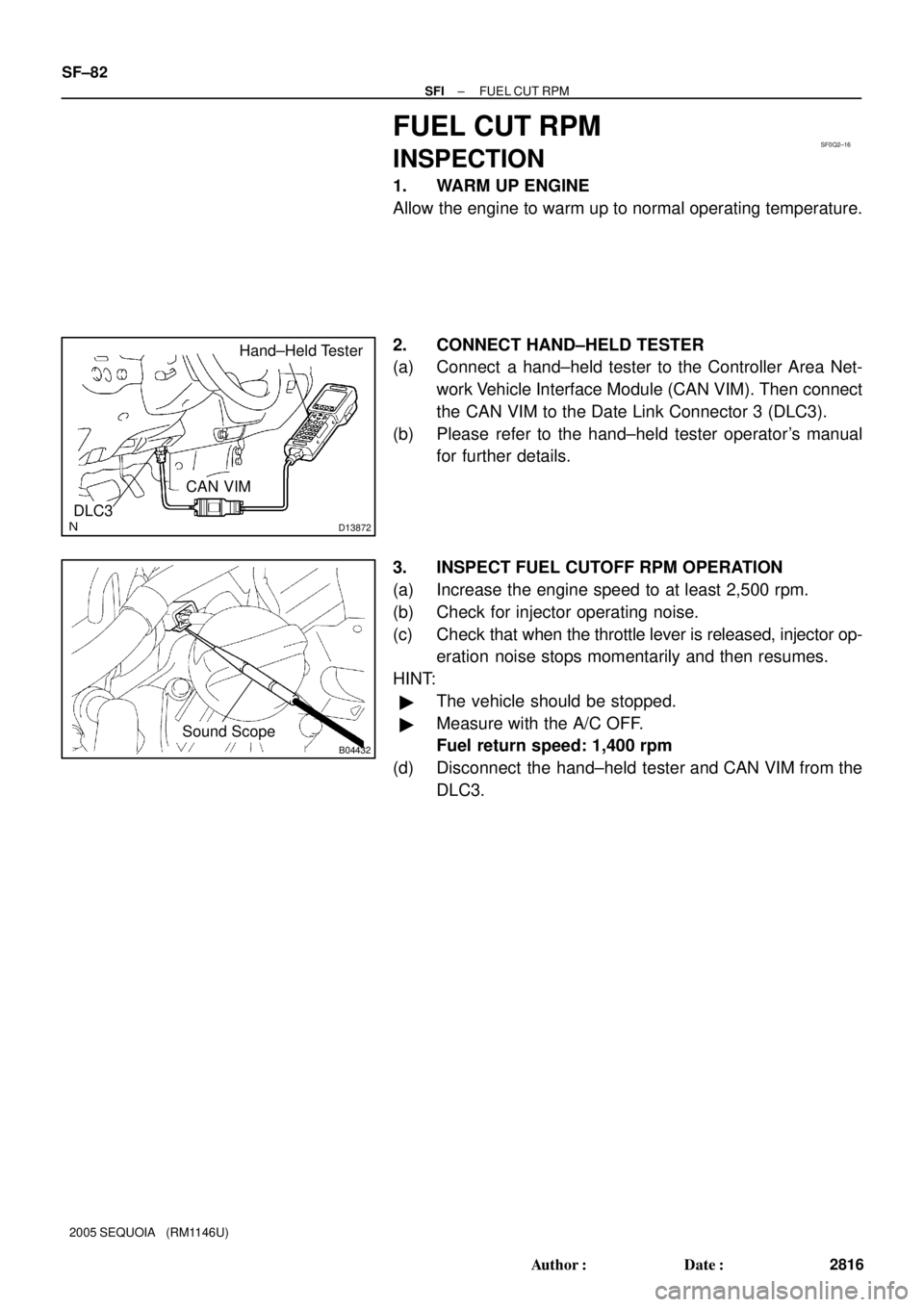
FUEL CUT RPM
INSPECTION
1. WARM UP ENGINE
Allow the engine to warm up to normal operating temperature.
2. CONNECT HAND±HELD TESTER
(a) Connect a hand±held tester to the Controller Area Net-
work Vehicle Interface Module (CAN VIM). Then connect
the CAN VIM to the Date Link Connector 3 (DLC3).
(b) Please refer to the hand±held tester operator's manual
for further details.
3. INSPECT FUEL CUTOFF RPM OPERATION
(a) Increase the engine speed to at least 2,500 rpm.
(b) Check for injector operating noise.
(c) Check that when the throttle lever is released, injector op-
eration noise stops momentarily and then resumes.
HINT:
�The vehicle should be stopped.
�Measure with the A/C OFF.
Fuel return speed: 1,400 rpm
(d) Disconnect the hand±held tester and CAN VIM from the
DLC3.
Page 2825 of 4323

COOLANT
INSPECTION
HINT:
Check the coolant level when the engine is cold.
1. CHECK ENGINE COOLANT LEVEL AT RADIATOR RESE")
CO0IO±07
± COOLINGCOOLANT
CO±1
2817 Author�: Date�:
2005 SEQUOIA (RM1146U)
COOLANT
INSPECTION
HINT:
Check the coolant level when the engine is cold.
1. CHECK ENGINE COOLANT LEVEL AT RADIATOR RESERVOIR
The engine coolant level should be between the ºLOWº and ºFULLº lines at normal temperature
(20°C(68°F)).
If low, check for leaks and add ºToyota Super Long Life Coolantº or similar high quality ethylene glycol based
non±silicate, non±amine, non±nitrite, and non±borate coolant with long±life hybrid organic acid technology
up to the ºFULLº line.
2. CHECK ENGINE COOLANT QUALITY
(a) Remove the radiator cap.
CAUTION:
To avoid the danger of being burned, do not remove the radiator cap while the engine and radiator
are still hot, as fluid and steam can be blown out under pressure.
(b) There should not be any excessive deposits of rust or scale around the radiator cap or radiator filler
hole, and the coolant should be free from oil.
If excessively dirty, clean the coolant passages and replace the coolant.
(c) Reinstall the radiator cap.
Page 2826 of 4323

REPLACEMENT
CAUTION:
To avoid the danger of being burned, do not remove the ra-
di")
CO0IP±12
B05864Drain PlugDrain Plug Drain Plug
CO±2
± COOLINGCOOLANT
2818 Author�: Date�:
2005 SEQUOIA (RM1146U)
REPLACEMENT
CAUTION:
To avoid the danger of being burned, do not remove the ra-
diator cap while the engine and radiator are still hot, as fluid
and steam can be blown out under pressure.
1. REMOVE ENGINE UNDER COVER
2. DRAIN ENGINE COOLANT
(a) Remove the radiator cap.
(b) Remove the 3 drain plugs on the engine and radiator, and
drain the coolant.
(c) Close the 3 drain plugs.
Torque: 12.7 N´m (130 kgf´cm, 9 ft´lbf) for engine
3. REFILL WITH ENGINE COOLANT
(a) Slowly fill the system with coolant.
Capacity: 11.6 liters (12.3 US qts, 10.2 Imp. qts)
NOTICE:
Do not use plain water alone.
HINT:
�Use of improper coolants may damage the engine cooling
system.
�Use ºToyota Super Long Life Coolantº or similar high qual-
ity ethylene glycol based non±silicate, non±amine, non±
nitrite, and non±borate coolant with long±life hybrid or-
ganic acid technology.
�New Toyota vehicles are filled with Toyota Super Long
Life Coolant (color is pink, premixed ethylene glycol con-
centration is approximately 50 % and freezing tempera-
ture is ±35°C (±31°F)). When replacing the coolant, Toyo-
ta Super long Life Coolant is recommended.
�Observe the coolant level inside the radiator by pressing
the inlet and outlet radiator hoses several times by hand.
if the coolant level goes down, add the coolant.
(b) Install the radiator cap.
(c) Bleed the cooling system.
(1) Start the engine, and open the heater water valve.
(2) Maintain the engine speed at 2,000 ± 2,500 rpm,
and warm up the engine.
(d) Stop the engine, and wait until the engine coolant cools
down.
(e) Refill coolant into the reservoir until it is ºFULLº.
4. CHECK FOR ENGINE COOLANT LEAKS
5. CHECK ENGINE COOLANT SPECIFIC GRAVITY COR-
RECTLY
6. REINSTALL ENGINE UNDER COVER
 : Specified torqueHeated Oxygen
Sensor Connector
Heated Oxygen Sensor
Engine Under CoverBank 2 Sensor 1
44 (450, 32)
Bank 1 Sensor 1
Heated Oxygen
Sensor Connec")
")

2814")