Page 2880 of 4323
IG08X±05
B07251
± IGNITIONCRANKSHAFT POSITION SENSOR
IG±11
2872 Author�: Date�:
2005 SEQUOIA (RM1146U)
REMOVAL
1. REMOVE ENGINE UNDER COVER
2. REMOVE CRANKSHAFT POSITION SENSOR
(a) Disconnect the crankshaft position sensor connector.
(b) Remove the bolt and crankshaft position sensor.
Page 2882 of 4323
IG0EM±04
B07251
± IGNITIONCRANKSHAFT POSITION SENSOR
IG±13
2874 Author�: Date�:
2005 SEQUOIA (RM1146U)
INSTALLATION
1. INSTALL CRANKSHAFT POSITION SENSOR
(a) Install the crankshaft position sensor with the bolt.
Torque: 6.5 N´m (65 kgf´cm, 58 in.´lbf)
(b) Connect the crankshaft position sensor connector.
2. INSTALL ENGINE UNDER COVER
Page 2883 of 4323
ST08X±03
± STARTINGSTARTING SYSTEM
ST±1
2875 Author�: Date�:
2005 SEQUOIA (RM1146U)
STARTING SYSTEM
ON±VEHICLE INSPECTION
NOTICE:
Before changing the starter, check these items again:
�Connector connection
�Accessory installation, e.g.: engine immobilizer system
Page 2885 of 4323
B17496
Injector Connector
VSV Connector
for EVAP
Starter ConnectorStarterIntake Manifold Assembly Engine Wire and Clamp
� Gasket
� Non±reusable part
39 (400, 29)
Engine Wire
Protector
Fuel Return Hose
Engine Wire
N´m (kgf´cm, ft´lbf) : Specified torque� GasketFuel Inlet Hose
Air Switching Valve No.2
� Gasket
� Gasket
10 (102, 7 )
10 (102, 7 )
10 (102, 7 )
10 (102, 7 )
± STARTINGSTARTER
ST±3
2877 Author�: Date�:
2005 SEQUOIA (RM1146U)
Page 2887 of 4323
ST08Z±07
B04548
B04549
Starter
Connector
Engine Wire Protector
± STARTINGSTARTER
ST±5
2879 Author�: Date�:
2005 SEQUOIA (RM1146U)
REMOVAL
1. REMOVE THROTTLE BODY COVER
2. REMOVE INTAKE AIR CONNECTOR
3. DISCONNECT CABLE FROM NEGATIVE (±) BATTERY
TERMINAL
4. DISCONNECT THROTTLE BODY ASSEMBLY FROM
INTAKE MANIFOLD (See page SF±42)
5. REMOVE INTAKE MANIFOLD ASSEMBLY
(See page EM±36)
6. REMOVE AIR PUMP ASSEMBLY (See page EC±22)
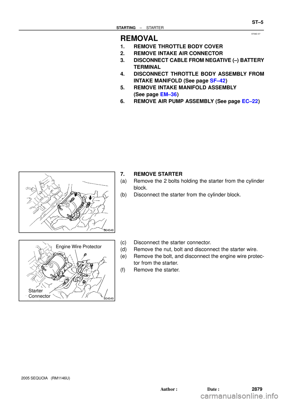
7. REMOVE STARTER
(a) Remove the 2 bolts holding the starter from the cylinder
block.
(b) Disconnect the starter from the cylinder block.
(c) Disconnect the starter connector.
(d) Remove the nut, bolt and disconnect the starter wire.
(e) Remove the bolt, and disconnect the engine wire protec-
tor from the starter.
(f) Remove the starter.
Page 2898 of 4323
ST095±06
B04549
Starter
Connector
Engine Wire Protector
B04548
ST±16
± STARTINGSTARTER
2890 Author�: Date�:
2005 SEQUOIA (RM1146U)
INSTALLATION
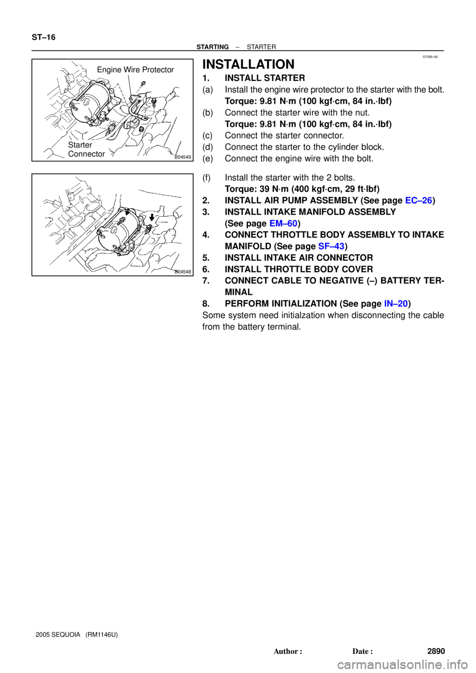
1. INSTALL STARTER
(a) Install the engine wire protector to the starter with the bolt.
Torque: 9.81 N´m (100 kgf´cm, 84 in.´lbf)
(b) Connect the starter wire with the nut.
Torque: 9.81 N´m (100 kgf´cm, 84 in.´lbf)
(c) Connect the starter connector.
(d) Connect the starter to the cylinder block.
(e) Connect the engine wire with the bolt.
(f) Install the starter with the 2 bolts.
Torque: 39 N´m (400 kgf´cm, 29 ft´lbf)
2. INSTALL AIR PUMP ASSEMBLY (See page EC±26)
3. INSTALL INTAKE MANIFOLD ASSEMBLY
(See page EM±60)
4. CONNECT THROTTLE BODY ASSEMBLY TO INTAKE
MANIFOLD (See page SF±43)
5. INSTALL INTAKE AIR CONNECTOR
6. INSTALL THROTTLE BODY COVER
7. CONNECT CABLE TO NEGATIVE (±) BATTERY TER-
MINAL
8. PERFORM INITIALIZATION (See page IN±20)
Some system need initialzation when disconnecting the cable
from the battery terminal.
Page 2901 of 4323

CHARGING SYSTEM
ON±VEHICLE INSPECTION
C")
CH0K7±03
B07241
Upper Level
Lower Level
B07242
Except Maintenance±Free Battery
± CHARGINGCHARGING SYSTEM
CH±1
2893 Author�: Date�:
2005 SEQUOIA (RM1146U)
CHARGING SYSTEM
ON±VEHICLE INSPECTION
CAUTION:
�Check that the battery cables are connected to the
correct terminals.
�Disconnect the battery cables when the battery is giv-
en a quick charge.
�Do not perform tests with a high voltage insulation re-
sistance tester.
�Never disconnect the battery while the engine is run-
ning.
1. CHECK BATTERY ELECTROLYTE LEVEL
Check the electrolyte quantity of each cell.
If under the lower level, replace the battery (or add distilled wa-
ter if possible) and check the charging system.
2. Except Maintenance±Free Battery:
CHECK BATTERY SPECIFIC GRAVITY
Check the specific gravity of each cell.
Standard specific gravity:
1.25 to 1.29 at 20°C (68°F)
If the specific gravity is less than the specification, charge the
battery.
3. Maintenance±Free Battery:
CHECK BATTERY VOLTAGE
(a) In the case that 20 minutes have not passe4d after stop-
ping the engine, turn on the ignition switch and the electri-
cal system (headlight, blower motor, rear defogger, etc.)
for 60 seconds before removing the surface charge.
(b) Turn the ignition switch OFF and turn off the electrical sys-
tems.
Page 2903 of 4323

�Check that t")
B00808
B
A
AC2024
CORRECT WRONG
Z03473
Ammeter
Disconnect Wire
from Terminal B
Battery
VoltmeterB
Generator
± CHARGINGCHARGING SYSTEM
CH±3
2895 Author�: Date�:
2005 SEQUOIA (RM1146U)
�Check that the arrow mark on the belt tensioner falls
within area A of the scale.
If it is outside area A, replace the drive belt.
HINT:
�When a new belt is installed, it should lie within area B. If
not, the drive belt is not correct.
�After installing a belt, check that it fits properly in the
ribbed grooves.
�Check by hand to confirm that the belt does not slipped
out of the groove on the bottom of the pulley.
6. REMOVE ENGINE UNDER COVER NO.1
7. VISUALLY CHECK GENERATOR WIRING AND LIS-
TEN FOR ABNORMAL NOISES
(a) Check that the wiring is in good condition.
(b) Check that there is no abnormal noise from the generator
while the engine is running.
8. CHECK CHARGE WARNING LIGHT CIRCUIT
(a) Warm up the engine and then turn it off.
(b) Switch off all accessories.
(c) Turn the ignition switch ON, and check that the charge
warning light comes on.
(d) Start the engine, and check that the light goes off.
If the light does not go off as specified, troubleshoot the charge
light circuit.
9. INSPECT CHARGING CIRCUIT WITHOUT LOAD
HINT:
If a battery/generator tester is available, connect the tester to
the charging circuit as per manufacturer's instructions.
(a) If a tester is not available, connect a voltmeter and amme-
ter to the charging circuit as follows:
�Disconnect the wire from terminal B of the genera-
tor, and connect it to the negative (±) tester probe
of the ammeter.
�Connect the positive (+) tester probe of the amme-
ter to terminal B of the generator.
�Connect the positive (+) tester probe of the voltme-
ter to terminal B of the generator.
�Ground the negative (±) tester probe of the voltme-
ter.
(b) Check the charging circuit as follows:
With the engine running from idling to 2,000 rpm, check
the reading on the ammeter and voltmeter.
Standard amperage: 10 A or less
Standard voltage: 13.2 to 14.0 V