Page 2904 of 4323
CH±4
± CHARGINGCHARGING SYSTEM
2896 Author�: Date�:
2005 SEQUOIA (RM1146U)
If the voltmeter reading is more than the standard voltage, re-
place the voltage regulator.
If the voltmeter reading is less than the standard voltage, check
the voltage regulator and generator.
10. INSPECT CHARGING CIRCUIT WITH LOAD
(a) With the engine running at 2,000 rpm, turn on the high
beam headlights and set the heater blower switch to HI.
(b) Check the reading on the ammeter.
Standard amperage: 30 A or more
If the ammeter reading is less than the standard amperage, re-
pair the generator.
HINT:
If the battery is fully charged, the indication will sometimes be
less than standard amperage.
11. REINSTALL ENGINE UNDER COVER
Page 2905 of 4323
CH073±08
B16569
Generator Connector
Generator Wire
N´m (kgf´cm, ft´lbf): Specified torque
39 (400, 29)
Engine Under Cover
x 5 Drive BeltWire ClampPS Vane Pump
39 (400, 29)
Terminal Cap
Intake Air ConnectorThrottle Body Cover
39 (400, 29)
39 (400, 29)
15.5 (158, 11)
Generator
9.8 (100, 87 in.´lbf)
± CHARGINGGENERATOR
CH±5
2897 Author�: Date�:
2005 SEQUOIA (RM1146U)
GENERATOR
COMPONENTS
Page 2907 of 4323
CH0LY±02
B00809
± CHARGINGGENERATOR
CH±7
2899 Author�: Date�:
2005 SEQUOIA (RM1146U)
REMOVAL
1. REMOVE ENGINE UNDER COVER
2. REMOVE THROTTLE BODY COVER
3. DISCONNECT CABLE FROM NEGATIVE (±) BATTERY
TERMINAL
4. DISCONNECT INTAKE AIR CONNECTOR FROM
THROTTLE BODY
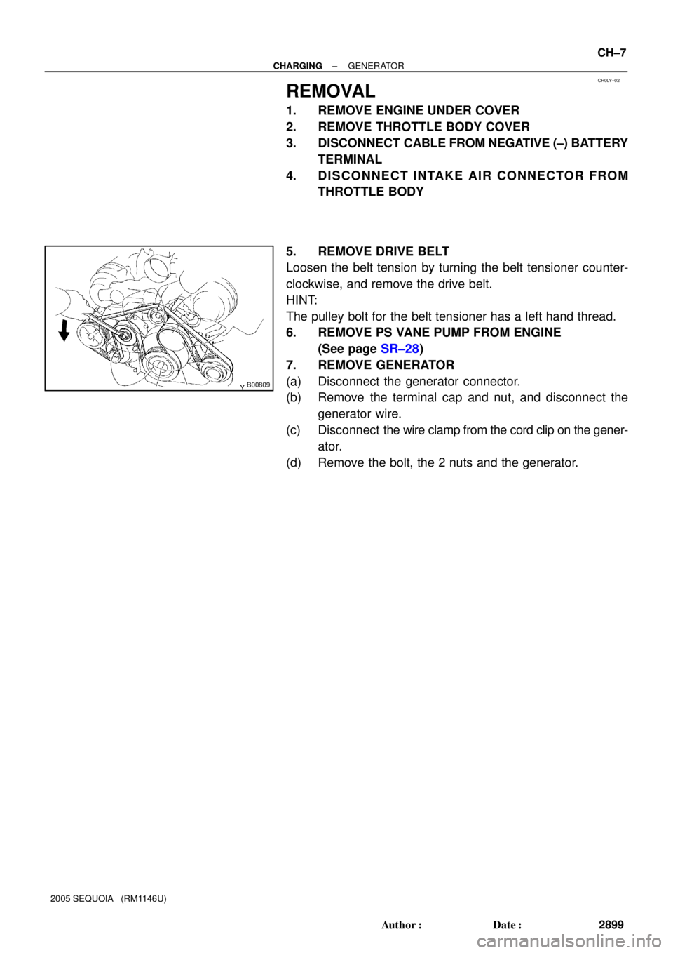
5. REMOVE DRIVE BELT
Loosen the belt tension by turning the belt tensioner counter-
clockwise, and remove the drive belt.
HINT:
The pulley bolt for the belt tensioner has a left hand thread.
6. REMOVE PS VANE PUMP FROM ENGINE
(See page SR±28)
7. REMOVE GENERATOR
(a) Disconnect the generator connector.
(b) Remove the terminal cap and nut, and disconnect the
generator wire.
(c) Disconnect the wire clamp from the cord clip on the gener-
ator.
(d) Remove the bolt, the 2 nuts and the generator.
Page 2916 of 4323

INSTALLATION
1. INSTALL GENERATOR
(a) Install the generator with the bolt and the 2 nuts.
Torque:
Bolt: 39 N")
CH0M3±02
B00809
CH±16
± CHARGINGGENERATOR
2908 Author�: Date�:
2005 SEQUOIA (RM1146U)
INSTALLATION
1. INSTALL GENERATOR
(a) Install the generator with the bolt and the 2 nuts.
Torque:
Bolt: 39 N´m (400 kgf´cm, 29 ft´lbf)
Nut 10 mm: 39 N´m (400 kgf´cm, 29 ft´lbf)
Nut 8 mm: 15.5 N´m (158 kgf´cm, 11 ft´lbf)
(b) Connect the generator connector.
(c) Connect the generator wire with the nut.
Torque: 9.8 N´m (100 kgf´cm, 87 in.´lbf)
(d) Install the terminal cap.
(e) Install the wire clamp to the cord clip on the generator.
2. INSTALL PS VANE PUMP (See page SR±36)
3. INSTALL DRIVE BELT
Install the belt by turning the belt tensioner counterclockwise.
HINT:
The pulley bolt for the belt tensioner has a left ± hand thread.
4. CONNECT INTAKE AIR CONNECTOR TO THROTTLE
BODY
5. PERFORM ON±VEHICLE INSPECTION
(See page CH±1)
6. INSTALL THROTTLE BODY COVER
7. INSTALL ENGINE UNDER COVER
8. CONNECT CABLE TO NEGATIVE (±) BATTERY TER-
MINAL
9. PERFORM INITIALIZATION (See page IN±20)
Some system need initialzation when disconnecting the cable
from the battery terminal.
Page 2939 of 4323
AT13E±01
D13873
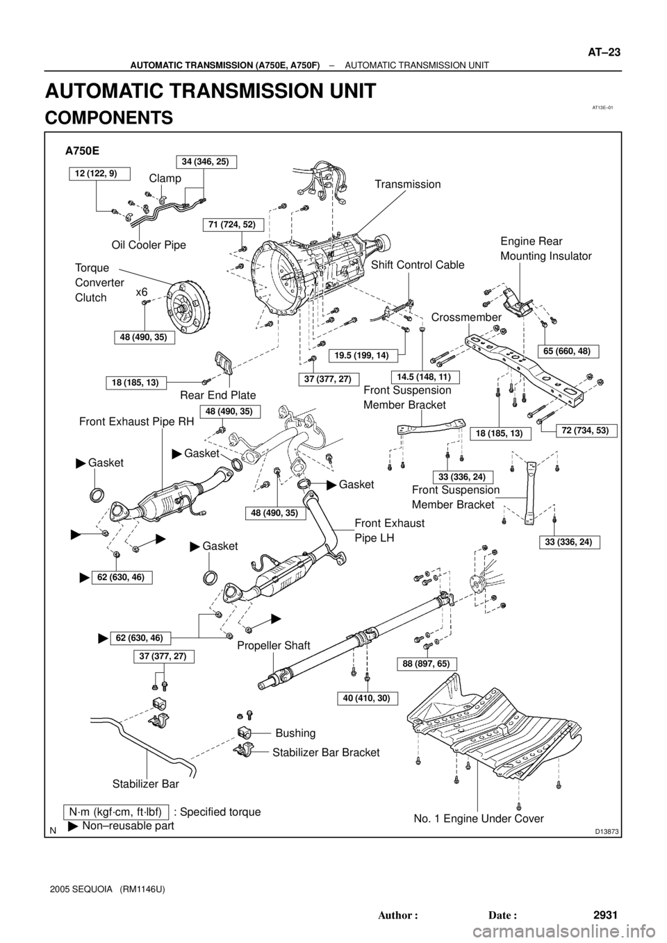
A750E
Clamp
Oil Cooler Pipe34 (346, 25)
Torque
Converter
Clutchx6
Transmission
48 (490, 35)
71 (724, 52)
Front Exhaust Pipe RH
N´m (kgf´cm, ft´lbf) : Specified torque
�Non±reusable part
37 (377, 27)
Stabilizer BarBushing
Stabilizer Bar Bracket
No. 1 Engine Under Cover
40 (410, 30)
88 (897, 65)
18 (185, 13)
CrossmemberEngine Rear
Mounting Insulator
Shift Control Cable
37 (377, 27)
Gasket �
Front Exhaust
Pipe LH
Rear End Plate
18 (185, 13)
Gasket �
�62 (630, 46)
� �
62 (630, 46)
�
� Gasket
Propeller Shaft
19.5 (199, 14)
14.5 (148, 11)
65 (660, 48)
72 (734, 53)
33 (336, 24)
33 (336, 24)
�
� Gasket
48 (490, 35)
Front Suspension
Member Bracket Front Suspension
Member Bracket
12 (122, 9)
48 (490, 35)
± AUTOMATIC TRANSMISSION (A750E, A750F)AUTOMATIC TRANSMISSION UNIT
AT±23
2931 Author�: Date�:
2005 SEQUOIA (RM1146U)
AUTOMATIC TRANSMISSION UNIT
COMPONENTS
Page 2940 of 4323
D13874
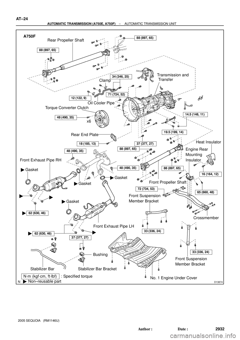
A750F
N´m (kgf´cm, ft´lbf) : Specified torque
�Non±reusable part
37 (377, 27)
Stabilizer Bar
Bushing
Stabilizer Bar Bracket
No. 1 Engine Under Cover
18 (185, 13)
Rear End Plate
Torque Converter Clutch
x6
48 (490, 35)
Oil Cooler Pipe
34 (346, 25)
Gasket �
Front Exhaust Pipe RH
Gasket �
� Gasket
37 (377, 27)
Crossmember
Engine Rear
Mounting
Insulator
19.5 (199, 14)
14.5 (148, 11)
Transmission and
Transfer
88 (897, 65)
Rear Propeller Shaft88 (897, 65)
Front Propeller Shaft
Heat Insulator
Front Exhaust Pipe LH
Clamp
71 (724, 52)
� Gasket
48 (490, 35)
16 (164, 12)
65 (660, 48)
88 (897, 65)
88 (897, 65)
72 (734, 53)
Front Suspension
Member Bracket
33 (336, 24)
Front Suspension
Member Bracket
33 (336, 24)
��
�62 (630, 46)
�62 (630, 46)�
12 (122, 9)
48 (490, 35)
AT±24
± AUTOMATIC TRANSMISSION (A750E, A750F)AUTOMATIC TRANSMISSION UNIT
2932 Author�: Date�:
2005 SEQUOIA (RM1146U)
Page 2941 of 4323
AT13F±01
D13882
D13867
± AUTOMATIC TRANSMISSION (A750E, A750F)AUTOMATIC TRANSMISSION UNIT
AT±25
2933 Author�: Date�:
2005 SEQUOIA (RM1146U)
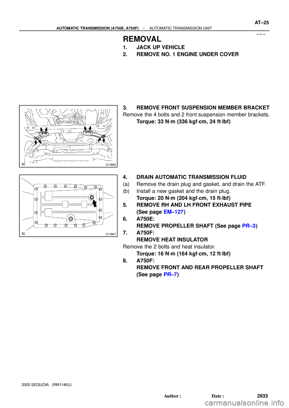
REMOVAL
1. JACK UP VEHICLE
2. REMOVE NO. 1 ENGINE UNDER COVER
3. REMOVE FRONT SUSPENSION MEMBER BRACKET
Remove the 4 bolts and 2 front suspension member brackets.
Torque: 33 N´m (336 kgf´cm, 24 ft´lbf)
4. DRAIN AUTOMATIC TRANSMISSION FLUID
(a) Remove the drain plug and gasket, and drain the ATF.
(b) Install a new gasket and the drain plug.
Torque: 20 N´m (204 kgf´cm, 15 ft´lbf)
5. REMOVE RH AND LH FRONT EXHAUST PIPE
(See page EM±127)
6. A750E:
REMOVE PROPELLER SHAFT (See page PR±3)
7. A750F:
REMOVE HEAT INSULATOR
Remove the 2 bolts and heat insulator.
Torque: 16 N´m (164 kgf´cm, 12 ft´lbf)
8. A750F:
REMOVE FRONT AND REAR PROPELLER SHAFT
(See page PR±7)
Page 2944 of 4323
D13883
D14131
A750E:
A750F:
D14132
17 mm
Head17 mm Head
14 mm Head
AT±28
± AUTOMATIC TRANSMISSION (A750E, A750F)AUTOMATIC TRANSMISSION UNIT
2936 Author�: Date�:
2005 SEQUOIA (RM1146U)
17. REMOVE CROSSMEMBER
(a) Remove the 4 bolts of the engine rear mounting on the
crossmember.
Torque: 18 N´m (185 kgf´cm, 13 ft´lbf)
(b) Remove the 4 nuts, bolts, washers and crossmember.
Torque: 72 N´m (734 kgf´cm, 53 ft´lbf)
18. REMOVE ENGINE REAR MOUNTING INSULATOR
Remove the 4 bolts and engine rear mounting insulator.
Torque: 65 N´m (660 kgf´cm, 48 ft´lbf)
19. REMOVE TRANSMISSION
(a) A750E:
Separate the wire harness from the transmission.
(b) A750F:
Separate the wire harness from the transmission and
transfer.
(c) Lower the rear end of the transmission.
(d) Remove the 10 bolts and transmission.
Torque:
17 mm head: 71 N´m (720 kgf´cm, 53 ft´lbf)
14 mm head: 37 N´m (380 kgf´cm, 27 ft´lbf)

: Specified torque
39 (400, 29)
Engine Under Cover
x 5 Drive BeltWire ClampPS Vane Pump
39 (400, 29)
Terminal Cap
Intake Air")