Page 3243 of 4323
F06726Vacuum Hose
SR01X±08
SR±8
± STEERINGAIR CONTROL VALVE
3235 Author�: Date�:
2005 SEQUOIA (RM1146U)
AIR CONTROL VALVE
INSPECTION
1. TURN AIR CONDITIONING SWITCH OFF
2. CHECK IDLE±UP
(a) Start the engine and run it at idle.
(b) Fully turn the steering wheel.
(c) Check that the engine speed decrease when the vacuum
hose of the air control valve is pinched.
(d) Check that the engine speed increase when the hose is
released.
Page 3244 of 4323
R07653
SR01Y±11
R09732
± STEERINGSTEERING WHEEL
SR±9
3236 Author�: Date�:
2005 SEQUOIA (RM1146U)
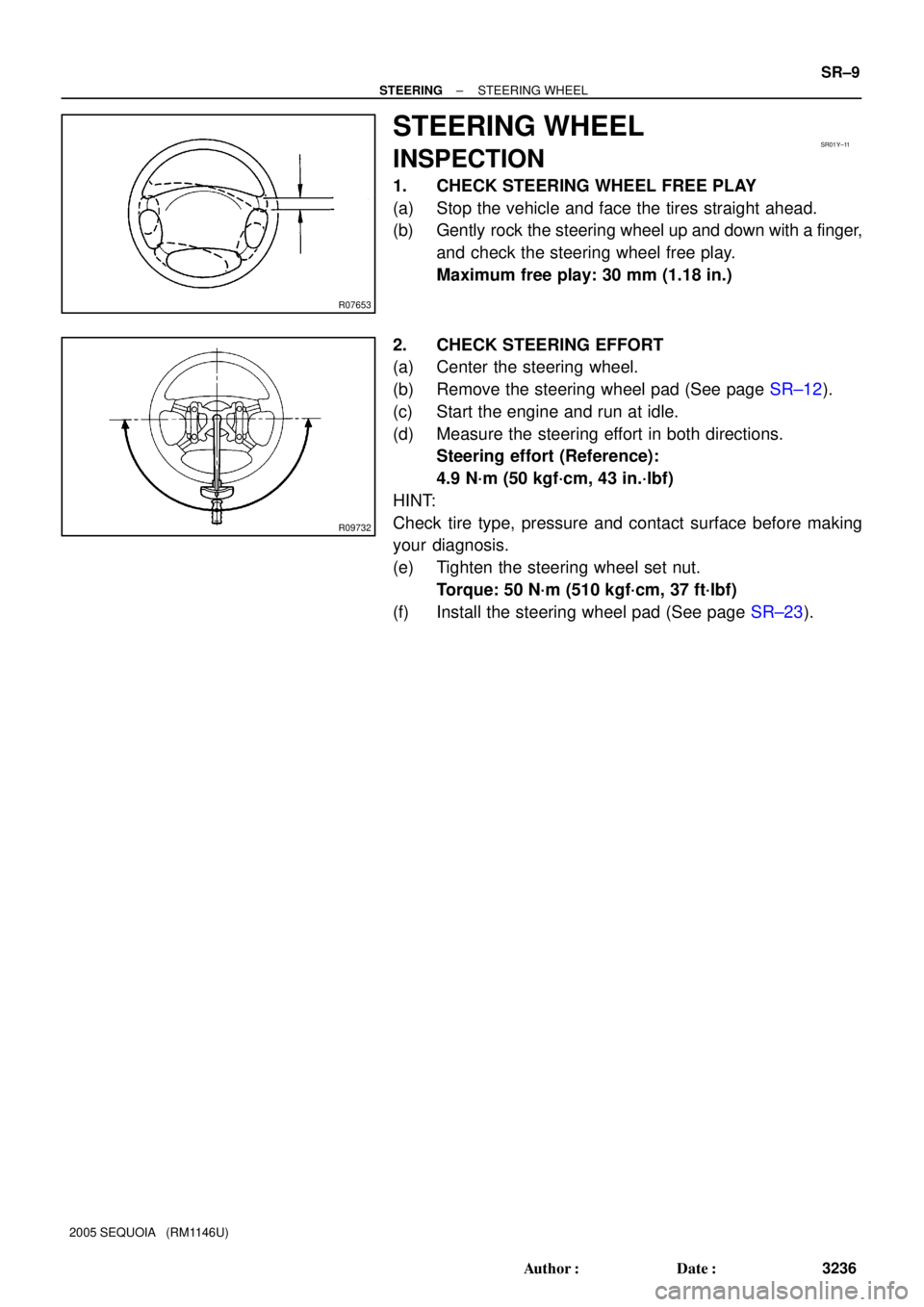
STEERING WHEEL
INSPECTION
1. CHECK STEERING WHEEL FREE PLAY
(a) Stop the vehicle and face the tires straight ahead.
(b) Gently rock the steering wheel up and down with a finger,
and check the steering wheel free play.
Maximum free play: 30 mm (1.18 in.)
2. CHECK STEERING EFFORT
(a) Center the steering wheel.
(b) Remove the steering wheel pad (See page SR±12).
(c) Start the engine and run at idle.
(d) Measure the steering effort in both directions.
Steering effort (Reference):
4.9 N´m (50 kgf´cm, 43 in.´lbf)
HINT:
Check tire type, pressure and contact surface before making
your diagnosis.
(e) Tighten the steering wheel set nut.
Torque: 50 N´m (510 kgf´cm, 37 ft´lbf)
(f) Install the steering wheel pad (See page SR±23).
Page 3417 of 4323
 Taillight does not go off when light control switch is in OFF posi-
tion.
1. TAILLIGHT Relay
2. Light Control Swit")
± BODY ELECTRICALTROUBLESHOOTING
BE±5
3409 Author�: Date�:
2005 SEQUOIA (RM1146U) Taillight does not go off when light control switch is in OFF posi-
tion.
1. TAILLIGHT Relay
2. Light Control Switch
3. Wire Harness
4. Body ECUBE±27
BE±27
±
±
Headlight does not come on when engine is running and light
control switch is in OFF position .
1. ECU±B Fuse
2. MAIN Fuse
3. HEAD Relay
4. DRL Fuse
5. DRL No. 4 Relay
6. DIMMER Relay
7. Parking Brake Switch
8. Wire Harness
9. Body ECUBE±14
BE±14
BE±27
BE±14
BE±27
BE±55
BE±55
±
±
FOG LIGHT SYSTEM
This system uses the multiplex communication system, so check diagnosis system of the multiplex commu-
nication system before you proceed with troubleshooting.
SymptomSuspect AreaSee page
Fog light does not come on with light control switch is in HEAD
position.
(Headlight is normal.)
1. FOG Fuse
2. FOG LIGHT Relay
3. Fog Light Switch
4. Wire Harness
5. Body ECUBE±14
BE±27
BE±34
±
±
Fog light does not come on with light control switch is in HEAD
position.
(Headlight does not light).1.*1 Other Parts
2. Wire Harness±
±
Only one light does not come on.1. Bulb
2. Wire Harness±
±
*1: Inspect Headlight System
TURN SIGNAL AND HAZARD WARNING SYSTEM
SymptomSuspect AreaSee page
ºHazardº and ºTurnº do not light up.
1. GAUGE Fuse
2. TURN±HAZ Fuse
3. Ignition Switch
4. Turn Signal Flasher Relay
5. Wire HarnessBE±14
BE±14
BE±24
BE±24
±
Hazard warning light does not light up.
(Turn is normal)1. Hazard Warning Switch
2. Wire Harness
3. Turn Signal Flasher RelayBE±36
±
BE±36
Turn signal does not light up.
(Hazard is normal)1. Turn Signal Switch
2. Wire Harness
3. Turn Signal Flasher RelayBE±36
±
BE±36
Turn signal does not light up in one direction.1. Bulb
2. Wire Harness±
±
Only one bulb does not light up.1. Bulb
2. Wire Harness±
±
INTERIOR LIGHT SYSTEM
This system uses the multiplex communication system, so check diagnosis system of the multiplex commu-
nication system before you proceed with troubleshooting.
SymptomSuspect AreaSee page
All the interior lights do not come on.
1. DOME Fuse
2. Illumination Circuit
3. Body ECUBE±14
DI±1759
±
Page 3421 of 4323

POWER DOOR LOCK CONTROL SYSTEM
This system uses the multiplex communication system, so check diagnosis system of t")
± BODY ELECTRICALTROUBLESHOOTING
BE±9
3413 Author�: Date�:
2005 SEQUOIA (RM1146U)
POWER DOOR LOCK CONTROL SYSTEM
This system uses the multiplex communication system, so check diagnosis system of the multiplex commu-
nication system before you proceed with troubleshooting.
SymptomSuspect AreaSee page
All the doors cannot be locked or unlocked.
(Power window control system is normal.)1. Door Unlock Detection Switch
2. Door Key Lock and Unlock Switch
3. Driver Door ECUBE±79
BE±79
±
Only one back lock control does not operate.
1. Back Door Lock Motor
2. Back Door Unlock Detection Switch
3. Back Door Key Lock and Unlock Switch
4. Back Door ECUBE±79
BE±79
BE±79
±
Driver door key related function does not operate.1. Door Key Lock and Unlock Switch
2. Driver Door ECUBE±79
±
Front passenger door key related function does not operate.1. Door Key Lock and Unlock Switch
2. Passenger Door ECUBE±79
±
Back door key related function does not operate.1. Door Key Lock and Unlock Switch
2. Back Door ECUBE±79
±
THEFT DETERRENT SYSTEM
This system uses the multiplex communication system, so check diagnosis system of the multiplex commu-
nication system before you proceed with troubleshooting.
SymptomSuspect AreaSee page
The theft deterrent system cannot be set.
1. Key Unlock Warning Switch Circuit
2. Door Unlock Detection Switch Circuit (Driver Door ECU)
Door Unlock Detection Switch Circuit (Passenger Door
ECU)
Door Unlock Detection Switch Circuit (Back Door ECU)
Door Unlock Detection Switch Circuit (Body ECU)
3. Engine Hood Courtesy Switch Circuit
4. Back Door Courtesy Light Switch
5. Courtesy Light Switch Circuit
6. Glass Breakage Sensor Circuit (*1)
7. Body ECUDI±1715
DI±1791
DI±1829
DI±1869
DI±1723
DI±1725
DI±1864
DI±1728
DI±1774
±
The system cannot be canceled when the ignition switch is turned
ON with a key.
1. AM1 Fuse
2. AM2 Fuse
3. Key Unlock Warning Switch Circuit
4. Ignition Switch
5. Body ECUBE±14
BE±14
DI±1715
BE±24
±
The system cannot be canceled when the back door is unlocked
with a key.
1. Back Door Unlock Detection Switch Circuit
2. Back Door Key Lock and Unlock Switch Circuit
3. Back door ECU
4. Body ECUDI±1869
DI±1882
±
±
The system does not operate when the engine hood is opened.1. Engine Hood Courtesy Switch Circuit
2. Body ECUDI±1725
±
Some of the system does not operate.
(Headlight does not come on.)
1. Bulb
2. HEAD Relay
3. DIMMER Relay
4. DRL No. 4 Relay
5. Headlight Dimmer Switch
6. Light Control Switch
7. Wire Harness
8. Body ECU±
BE±27
BE±27
BE±27
BE±27
BE±27
±
±
Page 3424 of 4323

NAVIGATION SYSTEM
SymptomSuspect AreaSee page
Navigation system abnormal operation.See DIAGNOSIS SYSTEMDI±2172
R")
BE±12
± BODY ELECTRICALTROUBLESHOOTING
3416 Author�: Date�:
2005 SEQUOIA (RM1146U)
NAVIGATION SYSTEM
SymptomSuspect AreaSee page
Navigation system abnormal operation.See DIAGNOSIS SYSTEMDI±2172
REAR SEAT ENTERTAINMENT SYSTEM
SymptomSuspect AreaSee page
Rear seat entertainment system abnormal operation.See DIAGNOSIS SYSTEMDI±2083
REAR SEAT AUDIO SYSTEM
SymptomSuspect AreaSee page
Rear seat audio system abnormal operation.See DIAGNOSIS SYSTEMDI±2048
CLOCK SYSTEM
SymptomSuspect AreaSee page
Clock does not operate.TROUBLESHOOTING NO.1BE±127
Clock loses or gains time.TROUBLESHOOTING NO.2BE±127
GARAGE DOOR OPENER SYSTEM
SymptomSuspect AreaSee page
The equipment of which code has been registered does not oper-
ate.1. Garage Door Opener Switch
2. Wire Harness
3. *BE±134
±
±
LED does not come on. (Even though either switch is pressed.)1. Garage Door Opener Switch
2. Wire HarnessBE±134
±
LED does not come on. (Only one switch is pressed.)Garage Door Opener SwitchBE±134
* As the GARAGE DOOR OPENER on the vehicle side seems to be normal, check the OPENER on the
equipment side, of which code has been registered.
ENGINE IMMOBILISER SYSTEM
SymptomSuspect AreaSee page
Engine immobilizer system does not operate.See DIAGNOSIS SYSTEMBE±143
HORN SYSTEM
This system uses the multiplex communication system, so check diagnosis system of the multiplex commu-
nication system before you proceed with troubleshooting.
SymptomSuspect AreaSee page
Horn system does not operate.
1. HORN Fuse
2. HORN Relay Circuit
3. Horn Switch Circuit
4. Horn
5. Body ECUBE±14
BE±145
BE±145
BE±145
±
Horn blow all the time.
1. HORN Relay Circuit
2. Horn Switch Circuit
3. Body ECUBE±145
BE±145
±
One horn operates but the other horn does not operate.1. Horn
2. Wire HarnessBE±145
±
Page 3426 of 4323
BE2DG±03
I28397
Engine Room R/B No. 2
Engine Room J/B
� FL Block
Instrument Panel J/B
Driver Side R/BEngine Room R/B No. 3 FL Block:
A
B
B
A
B
Engine Room R/B
No. 4
NOTICE:
When removing the FL block, pinch ºAº using pliers and pull it out.
Since ºBº is easy to damage, do not pinch with pliers. BE±14
± BODY ELECTRICALPOWER SOURCE
3418 Author�: Date�:
2005 SEQUOIA (RM1146U)
POWER SOURCE
LOCATION
Page 3427 of 4323
I28398
Fuses:Relays:
1. *1 H±LP LL
2. *1 H±LP RL
3. STA
4. *1 H±LP LH
5. *1 H±LP RH
A
G
FED
BC
6
1034
5
A. AIR SUS Relay
B. CDS FAN Relay
C. MG CLT Relay
D. A/F Relay
E. *1 DRL No. 4 Relay
F. DIMMER Relay
G. ST Relay
*1 w/ Daytime Running Light Engine Room R/B No. 2
7
8
911
12
6. AIR SUS No. 2
7. RSE
8. A/F
9. SECURITY
10. DEF I/UP
11. ±
12. ±12
10 A
10 A
7.5 A
10 A
10 A
10 A
7.5 A
20 A
15 A
7.5 A
± BODY ELECTRICALPOWER SOURCE
BE±15
3419 Author�: Date�:
2005 SEQUOIA (RM1146U)
Page 3429 of 4323

I28399
Fusible Link Block:
Relays: Fuses:
5. RR HEATER Fuse 30 A
A. C/OPN Relay
B. HEAD Relay
C. EFI Relay
D. FUEL PUMP Relay
E. DEFOG Relay
F. HORN Relay
Engine Room J/B6. R/B Fuse 30 A
7. A/PUMP Fuse 50 A
8. ABS Fuse 60 A
9. ALT Fuse 140 A
10. CDS FAN Fuse 25 A
11. Spare Fuse 15 A
12. Spare Fuse 20 A
13. Spare Fuse 30 A
14. Main Fuse 40 A
15. DOOR No. 2 Fuse 30 A
16. *2 H±LP RH Fuse 15 A
17. EFI No. 1 Fuse 20 A
18. ETCS Fuse 10 A19. *1.DRL Fuse 15 A
*2.H±LP LH Fuse 15 A
20. ALT±S Fuse 7.5 A
21. TOWING Fuse 30 A
22. ST Fuse 30 A
23. RAD No. 3 Fuse 30 A
24. TURN±HAZ Fuse 20 A
25. AM2 Fuse 25 A
26. EFI No. 2 Fuse 10 A
27. SHORT±PIN
28. HORN Fuse 10 A
29. MIR HTR Fuse 15 A
30. ECU±B Fuse 7.5 A
31. DOME Fuse 10 A
32. RAD No. 1 Fuse 20 A
*1 w/ Daytime Running Light
*2 w/o Daytime Running Light 15
16 17 18
19 20 21
262728
2930
A
B
C
D
EF 1
234
5
6789
10
22 2324 25
31
32
11
12
13141. TOWING R/B Fuse 50 A
2. AIR SUS Fuse 50 A
3. HEATER Fuse 50 A
4. DEFOG Fuse 40 A
± BODY ELECTRICALPOWER SOURCE
BE±17
3421 Author�: Date�:
2005 SEQUOIA (RM1146U)