Page 3469 of 4323

I01279
Warning Light
Ignition
Switch
Battery
I19428
21OFF
ON
N01212
BE1217
Warning Light
Ignition
Switch
Battery
± BODY ELECTRICALCOMBINATION METER
BE±57
3461 Author�: Date�:
2005 SEQUOIA (RM1146U)
7. INSPECT BRAKE WARNING LIGHT OPERATION
(a) Disconnect the connector from the brake fluid warning
switch.
(b) Release the parking brake pedal.
(c) Connect the terminals on the harness side of the level
warning switch connector.
(d) Start the engine and check that the warning light comes
on.
If the warning light does not come on, test the bulb or wire har-
ness.
8. INSPECT BRAKE FLUID LEVEL WARNING SWITCH
CONTINUITY
(a) Remove the reservoir tank cap and strainer.
(b) Disconnect the connector.
(c) Check that no continuity exists between the terminals with
the switch OFF (float up).
(d) Use siphon, etc. to drain fluid out of the reservoir tank.
(e) Check that continuity exists between the terminals with
the switch ON (float down).
(f) Pour the fluid back in the reservoir tank.
If continuity is not as specified, replace the switch.
9. INSPECT PARKING BRAKE SWITCH CONTINUITY
(a) Check that continuity exists between the terminal and
switch body with the switch ON (switch pin released).
(b) Check that no continuity exists between the terminal and
switch body with the switch OFF (switch pin pushed in).
If operation is not as specified, replace the switch or inspect
ground point.
10. INSPECT WASHER LEVEL WARNING LIGHT OPERA-
TION
(a) Disconnect the connectors from the combination meter.
(b) Connect the negative (±) lead from the battery to terminal
16.
(c) Turn the ignition switch ON and check that the warning
light comes on.
If the warning light does not come on, test the bulb.
Page 3476 of 4323
BE0TC±09
I28412
Mirror Assembly
� Mirror Heater
Rear Window Defogger
Instrument Panel J/B
� MIRROR HEATER Relay
Ignition Switch Rear Defogger SwitchEngine Room J/B
� DEFOG Relay
� MIR HTR Fuse
BE±64
± BODY ELECTRICALDEFOGGER SYSTEM
3468 Author�: Date�:
2005 SEQUOIA (RM1146U)
DEFOGGER SYSTEM
LOCATION
Page 3495 of 4323

Disarmed state
Perform any of the following and the system will go on to ºArming preparationº:
� With all the doors, the engine hood and the back door closed, lock all doors with the key.
� With all the doors, the engine hood and the back door closed, lock all doors by the
wireless remote control.
� With all the doors, engine hood and back door locked, open and close any of the doors, the
engine hood or the back door, then close and lock all doors, the engine hood and the back door.
Arming preparation
Perform the following and the system will
go on to ºArmed stateº:
� Let 30 seconds elapse with all the doors,
engine hood and the back door closed and
locked.
Perform any of the following and the system
will return to ºDisarmed stateº:
� Open any of the doors, the engine hood or
the back door .
� Unlock any of the doors or the back door.
� Put the key in the key cylinder.
� Reconnect the battery.
Armed state
Perform any of the following and the system
will return to ºDisarmed stateº:
� Unlock any of the doors or the back door by
the wireless remote control.
� Unlock any of the doors or the back door with
the key.
� Put the key in the key cylinder and turn it ON.
Perform any of the following and the system
will go on to ºAlarm soundingº:
� Open any of the doors or the back door.
� Unlock any of the doors or the back door in
any way other than with a key or by the wireless
remote control.
� Open the engine hood.
� Reconnect the battery.
� When input from the optional glass break sensor
is detected (Dealer option).(Key not inserted in key cylinder.)
Alarm sounding
The vehicle's horn and security horn will sound,
and the hazard, interior, tail and head lights come
on for 60 seconds.
After the alarm has stopped, the system will
return to ºArmed stateº. Perform any of the following and the system
will return to ºDisarmed stateº:
� Unlock any of the doors and the back door by
the wireless remote control.
� Unlock any of the doors or the back door with
the key.
� Put the key in the key cylinder and turn it ON.
± BODY ELECTRICALTHEFT DETERRENT SYSTEM
BE±83
3487 Author�: Date�:
2005 SEQUOIA (RM1146U)
2. ACTIVE ARMING MODE
Page 3503 of 4323
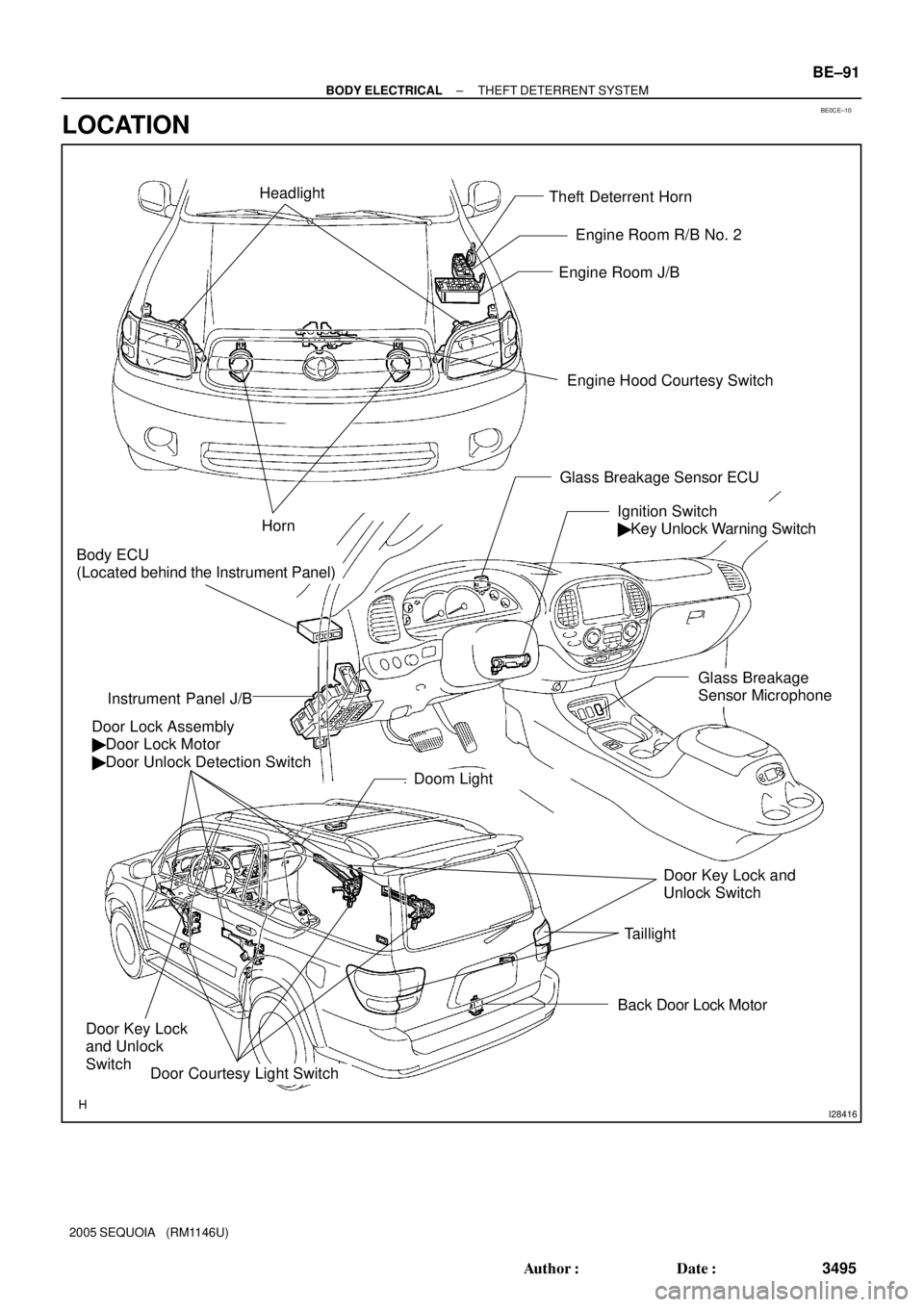
BE0CE±10
I28416
Theft Deterrent Horn
Engine Hood Courtesy Switch Engine Room J/B
Door Lock Assembly
� Door Lock Motor
� Door Unlock Detection Switch
Ignition Switch
� Key Unlock Warning Switch
Instrument Panel J/B
Door Courtesy Light Switch
Horn
Back Door Lock Motor
Door Key Lock
and Unlock
Switch
Door Key Lock and
Unlock Switch Headlight
Doom Light
Taillight
Body ECU
(Located behind the Instrument Panel)
Engine Room R/B No. 2
Glass Breakage Sensor ECU
Glass Breakage
Sensor Microphone
± BODY ELECTRICALTHEFT DETERRENT SYSTEM
BE±91
3495 Author�: Date�:
2005 SEQUOIA (RM1146U)
LOCATION
Page 3504 of 4323
I04146
BE1W8±05
I04148
ON OFF BE±92
± BODY ELECTRICALTHEFT DETERRENT SYSTEM
3496 Author�: Date�:
2005 SEQUOIA (RM1146U)
INSPECTION
1. INSPECT THEFT DETERRENT HORN OPERATION
Connect the positive (+) lead from the battery to terminal 1 and
negative (±) lead to the theft deterrent horn body, and check
that the theft deterrent horn blows.
If operation is not as specified, replace the horn.
2. INSPECT ENGINE HOOD COURTESY SWITCH CON-
TINUITY
Switch positionTester connectionSpecified condition
CLOSE (OFF)±No continuity
OPEN (ON)1 ± 2Continuity
If continuity is not as specified, replace the switch.
3. INSPECT ENGINE HOOD COURTESY SWITCH CIR-
CUIT (See page DI±1725)
Page 3549 of 4323

START
Insert the key in the key cylinder.
Under registration
Registration completion
Remove the key.
Will you register the
next key?
NoSecurity indicator blinks until the first
key is inserted. The indicator comes
on after the key registration.
Security Indicator
OFF
END Ye s
Security Indicator ON
(After the last key (sub±key) has been
registered, the indicator remains OFF
until the key is removed. After the key
is removed, the indicator blinks.)
± BODY ELECTRICALENGINE IMMOBILISER SYSTEM
BE±137
3541 Author�: Date�:
2005 SEQUOIA (RM1146U)
ENGINE IMMOBILISER SYSTEM
REGISTRATION PROCEDURE
HINT:
If you lose all the registered master keys, you cannot registrar or delete additionally. Change the transponder
key ECU and then register the new key codes following the registration procedure of the automatic registra-
tion mode below.
1. KEY REGISTRATION IN AUTOMATIC REGISTRATION MODE
(a) Registration of a new transponder key.
HINT:
�This procedure must be done when you install a new transponder key ECU.
�The new transponder key ECU is in automatic key code registration mode. The key codes already fixed
for this transponder key ECU can be registered.
For this type of vehicle, up to 3 key codes can be registered.
�In the automatic registration mode, the last key registered becomes a sub±key.
Page 3550 of 4323

1.8 Sec.
0.2 Sec.
0.25 Sec. 0.5 Sec.0.25 Sec.
1 Sec. Blinks
Code 2±1 Code 2±2
0.25 Sec.
0.25 Sec.0.5 Sec. 1 Sec. BE±138
± BODY ELECTRICALENGINE IMMOBILISER SYSTEM
3542 Author�: Date�:
2005 SEQUOIA (RM1146U)
HINT:
�When a key cannot be inserted in the key cylinder in automatic registration mode, the security indicator
always comes on.
�When the immobilizer system operates normally and the key is pull out, the security indicator blinks.
�When key code registration could not be performed in automatic registration mode, code 2±1 is output
from the security indicator and when the registered key in inserted, code 2±2 is output.
(b) Automatic registration mode completion
If completing the mode forcibly when more than 1 key codes are registered in automatic registration
mode, perform the following procedures.
After 1 more key codes are registered with the master key, turn the ignition switch LOCK "ON 5 times
within 10 secs. by inserting the registered key or without pulling the key out.
Page 3551 of 4323
START
END
All doors closed. No key in the key cylinder.
Insert the registered master key in the key cylinder.
Ignition switch: LOCK " ON 5 times
Driver's door: Open " Close 6 times
Remove the master key.
Insert the key to be registered in the key cylinder.
Keep ignition switch in ON position for 60 seconds or more.
Remove the master key.
Do you register another key?
Driver's door: Open " Close
within
15 secs.
within
20 secs.
within
10 secs.
within
10 secs.
within
10 secs.*6
*5 *4 *3 *2 *1
No Ye s
10 secs.
or
more
± BODY ELECTRICALENGINE IMMOBILISER SYSTEM
BE±139
3543 Author�: Date�:
2005 SEQUOIA (RM1146U)
2. REGISTRATION OF ADDITIONAL MASTER KEY AND SUB KEY
Do this operation to register an additional master key and sub key.