Page 3430 of 4323
I28550
Engine Room R/B No. 3:
Relays: Fuses:
1. TOWING BRK Fuse 30 A
A. BATT CHARGE Relay
B. TOWING TAIL Relay 2. BATT CHARGE Fuse 30 A
3. TOWING TAIL Fuse 30 A
Driver Side R/B:
Relays:
A. INVERTER Relay
B. SEAT HEATER RelayEngine Room R/B No. 4:
Relays:
A. RR HEATER Relay
B. HEATER Relay BE±18
± BODY ELECTRICALPOWER SOURCE
3422 Author�: Date�:
2005 SEQUOIA (RM1146U)
Page 3437 of 4323
BE0HV±12
I28402
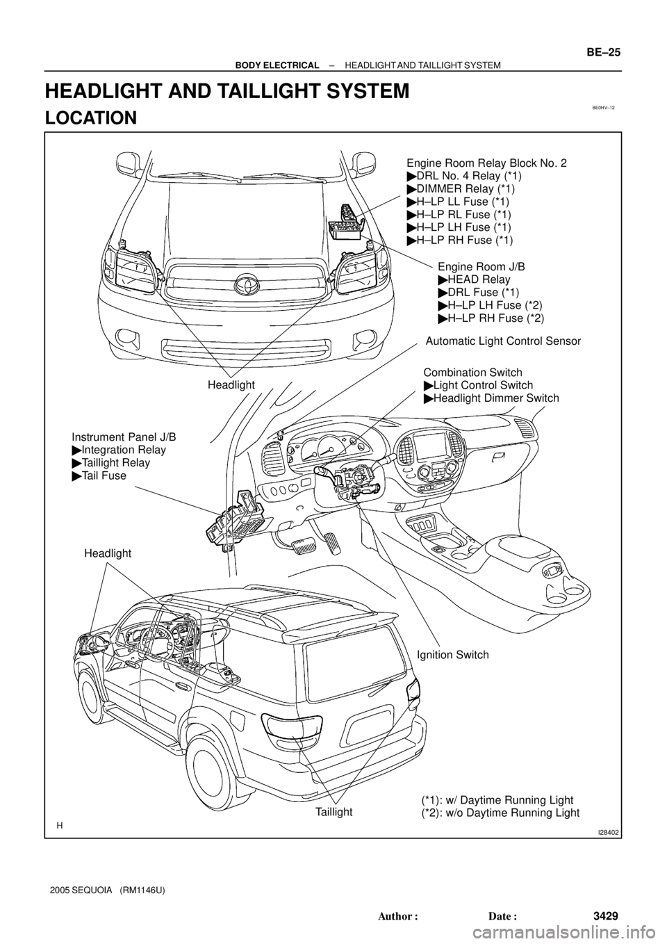
Engine Room Relay Block No. 2
� DRL No. 4 Relay (*1)
� DIMMER Relay (*1)
� H±LP LL Fuse (*1)
� H±LP RL Fuse (*1)
� H±LP LH Fuse (*1)
� H±LP RH Fuse (*1)
Headlight
Combination Switch
� Light Control Switch
� Headlight Dimmer Switch
Ignition Switch
Taillight
Instrument Panel J/B
� Integration Relay
� Taillight Relay
� Tail Fuse
Headlight
Engine Room J/B
� HEAD Relay
� DRL Fuse (*1)
� H±LP LH Fuse (*2)
� H±LP RH Fuse (*2)
Automatic Light Control Sensor
(*1): w/ Daytime Running Light
(*2): w/o Daytime Running Light
± BODY ELECTRICALHEADLIGHT AND TAILLIGHT SYSTEM
BE±25
3429 Author�: Date�:
2005 SEQUOIA (RM1146U)
HEADLIGHT AND TAILLIGHT SYSTEM
LOCATION
Page 3444 of 4323
 H 20.9 mm
(0.823 in.)
7
V RH Line
90 °
V LH Line4V LH LineV Line V RH Line 65
6
V LH LineV Line
V RH Line 6
5
6
H4
O: step No.H4
20.9 mm
(0.823 in.) 1,348 mm (53.1 in.)")
I18654
0.4 °
3 m (9.84 ft) H 20.9 mm
(0.823 in.)
7
V RH Line
90 °
V LH Line4V LH LineV Line V RH Line 65
6
V LH LineV Line
V RH Line 6
5
6
H4
O: step No.H4
20.9 mm
(0.823 in.) 1,348 mm (53.1 in.) Low Beam:
High Beam:29.7 mm
(1.17 in.)
20.9 mm
(0.823 in.)
1,348 mm (53.1 in.)
1,348 mm
(53.1 in.) High Beam
Low BeamH RH and
H LH
7
BE±32
± BODY ELECTRICALHEADLIGHT AND TAILLIGHT SYSTEM
3436 Author�: Date�:
2005 SEQUOIA (RM1146U)
2. ADJUST HEADLIGHT AIM ONLY
(a) Place the vehicle in the following conditions.
�The area around the headlight is not deformed.
�The vehicle is parked on a level surface.
�Tire inflation pressure is the specified value.
�A driver is in the driver's seat and the vehicle is in a state ready for driving (with a tank full).
�The vehicle has been bounced several times.
(b) Check the headlight aiming.
(1) Prepare a thick white paper.
(2) Stand the paper perpendicular to the ground at the position 3 m (9.84 ft) away from the headlights
bulb center.
(3) Ensure that the center line of the vehicle and the paper face forms a 90±degree angle as shown
in the illustration.
(4) Draw a horizontal line (H line) on the paper, showing where the headlights should strike.
(5) Draw a vertical line (V line) at the position where the extended center line of the vehicle strikes.
(6) Draw 2 vertical lines (by connecting the low and high beam center marks) to where the both head-
lights should strike (V RH and V LH lines).
(7) Draw a horizontal line (by connecting the both low beam center marks) at the position where the
headlights should strike (H RH and H LH lines).
HINT:
The H RH and H LH line is 0.4° below the horizontal line (H line) of the light axis.
(8) Start the engine.
(9) Turn the headlights ON.
(10) Check that the headlights properly strike the position shown in the illustration.
(11) If not, adjust the lights in the vertical or horizontal direction.
HINT:
As shown in the illustration, adjust each aim of the RH and LH lights.
(c) When adjusting it in the vertical direction:
Using adjusting bolt, adjust the headlight aim to within the specified range.
Page 3447 of 4323
BE033±09
I28404
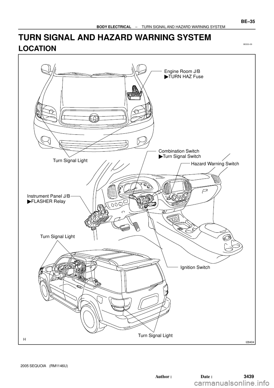
Turn Signal LightHazard Warning Switch Combination Switch
� Turn Signal Switch
Ignition Switch Instrument Panel J/B
� FLASHER Relay
Turn Signal Light
Turn Signal Light
Engine Room J/B
� TURN HAZ Fuse
± BODY ELECTRICALTURN SIGNAL AND HAZARD WARNING SYSTEM
BE±35
3439 Author�: Date�:
2005 SEQUOIA (RM1146U)
TURN SIGNAL AND HAZARD WARNING SYSTEM
LOCATION
Page 3450 of 4323
BE175±06
I28405
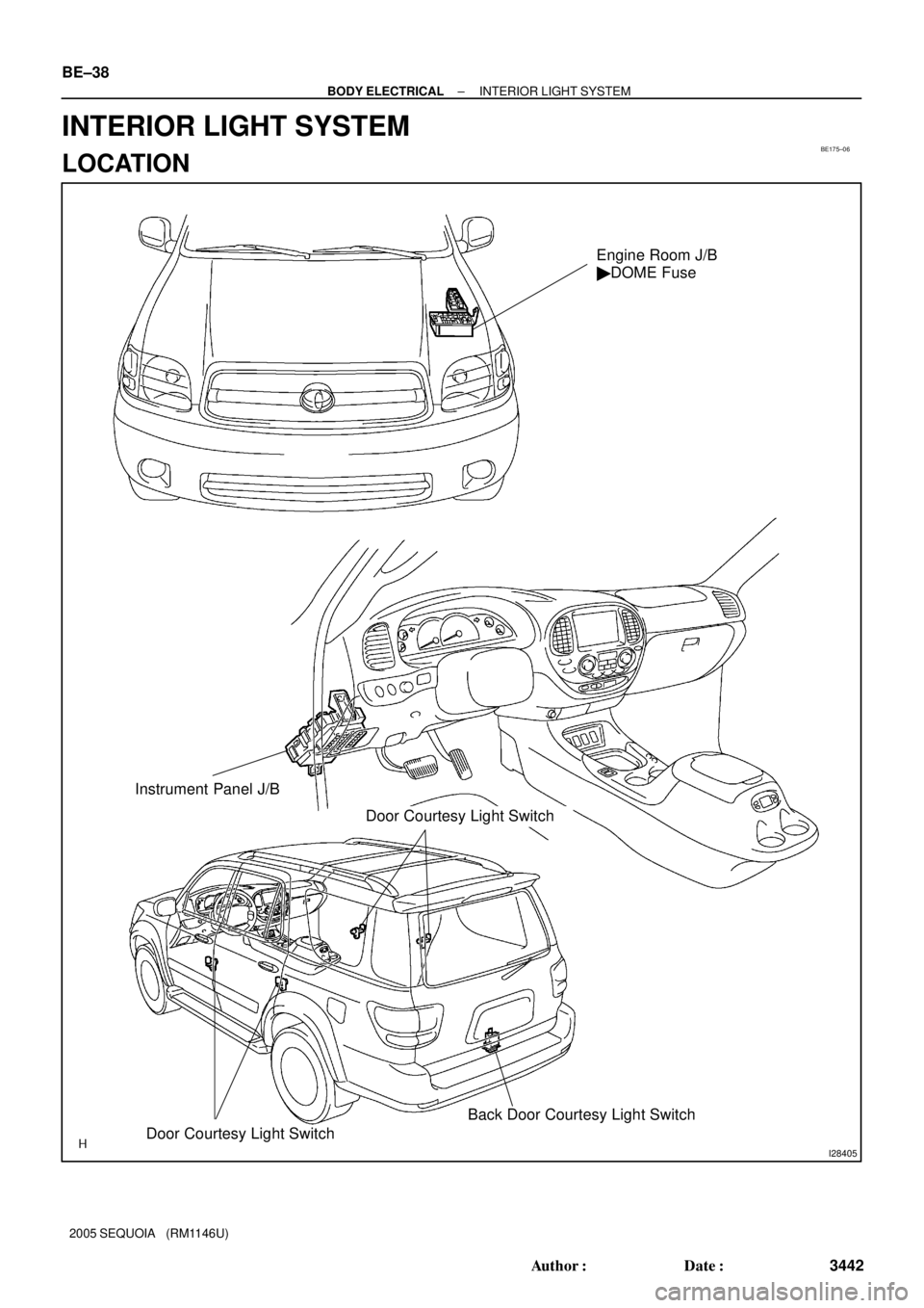
Door Courtesy Light SwitchBack Door Courtesy Light Switch
Engine Room J/B
� DOME Fuse
Instrument Panel J/B
Door Courtesy Light Switch
BE±38
± BODY ELECTRICALINTERIOR LIGHT SYSTEM
3442 Author�: Date�:
2005 SEQUOIA (RM1146U)
INTERIOR LIGHT SYSTEM
LOCATION
Page 3465 of 4323
BE17A±06
I28425
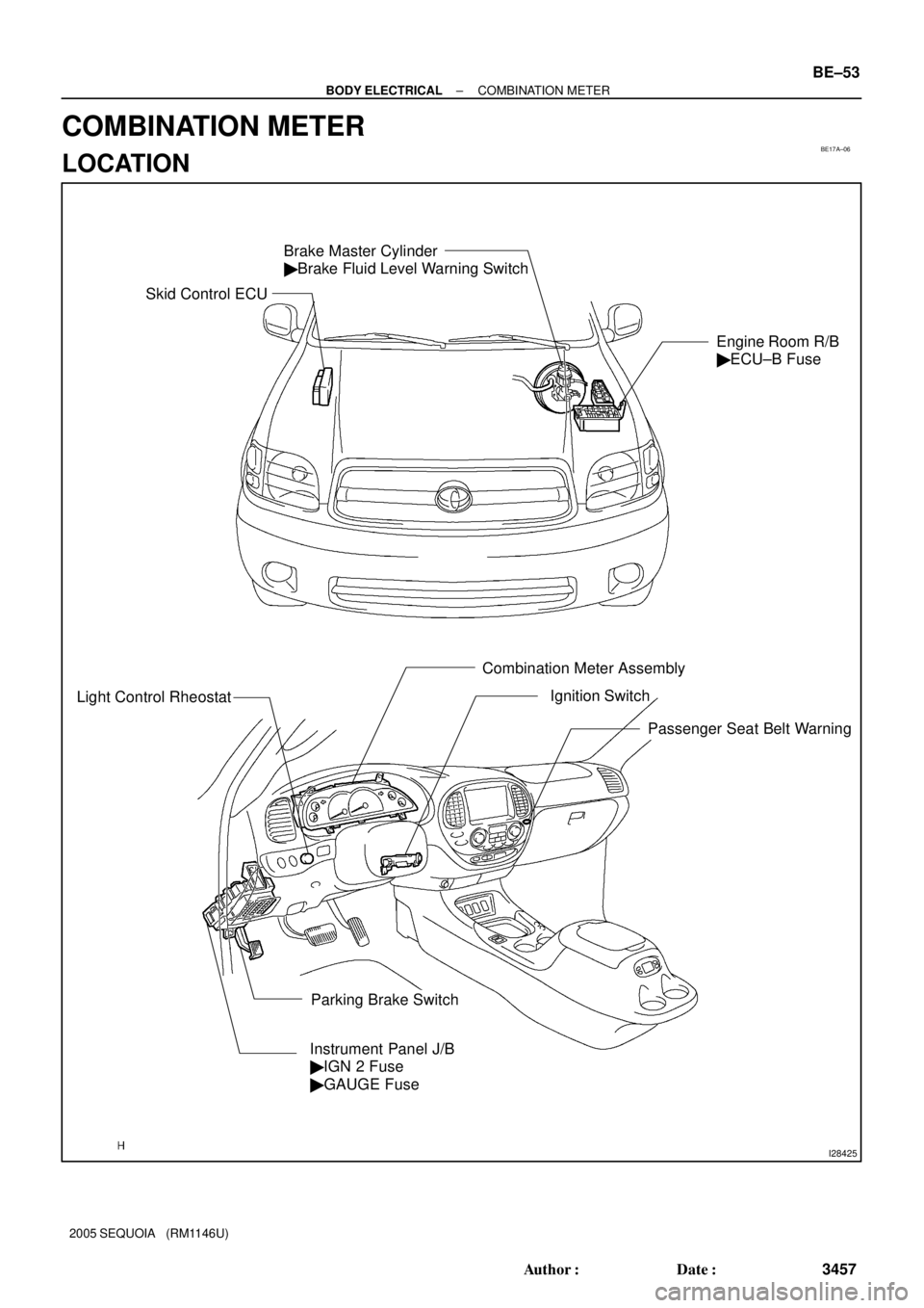
Brake Master Cylinder
� Brake Fluid Level Warning Switch
Engine Room R/B
� ECU±B Fuse
Light Control Rheostat
Combination Meter Assembly
Instrument Panel J/B
� IGN 2 Fuse
� GAUGE Fuse
Parking Brake SwitchIgnition Switch
Passenger Seat Belt Warning
Skid Control ECU
± BODY ELECTRICALCOMBINATION METER
BE±53
3457 Author�: Date�:
2005 SEQUOIA (RM1146U)
COMBINATION METER
LOCATION
Page 3467 of 4323

INSPECTION
1. INSPECT SPEEDOMETER ON±VEHICLE
Using a speedometer tester, inspect the speedome")
BE2MR±01
N06031
± BODY ELECTRICALCOMBINATION METER
BE±55
3459 Author�: Date�:
2005 SEQUOIA (RM1146U)
INSPECTION
1. INSPECT SPEEDOMETER ON±VEHICLE
Using a speedometer tester, inspect the speedometer for allow-
able indication error and check odometer operation.
HINT:
Tire wear and tire over or under inflation will increase the indica-
tion error.
USA (mph)CANADA (km/h)
Standard indication Allowable rangeStandard indication Allowable range
20 19 ± 2220 17.5 ± 21.5
40 39 ± 42.540 38 ± 42
60 59.5 ± 63.560 58 ± 63
80 79.5 ± 8480 78 ± 84
100 100 ± 105100 98.5 ± 104.5
±120 119 ± 125
±140 139 ± 145
±160 159 ± 167
If error is excessive, replace the speedometer.
2. INSPECT TACHOMETER
(a) Connect a tune±up test tachometer, and start the engine.
NOTICE:
�Reversing the connection of the tachometer will dam-
age the transistors and diodes inside.
�When removing or installing the tachometer, be care-
ful not to drop or subject it to heavy shocks.
(b) Compare the tester and tachometer indications.
DC 13.5 V 20°C at (68°F)
Standard indicationAllowable range
700630 ± 770
1,000900 ± 1,100
2,0001,850 ± 2,150
3,0002,800 ± 3,200
4,0003,800 ± 4,200
5,0004,800 ± 5,200
6,0005,750 ± 6,250
If error is excessive, replace the tachometer.
3. INSPECT FUEL RECEIVER GAUGE OPERATION
(a) Disconnect the connector from the sender gauge.
(b) Turn the ignition switch ON and check that the receiver
gauge needle indicates EMPTY.
Page 3468 of 4323
(3.4W) Fuel Gauge
Z05730
Warning Light
Ignition
Switch
Battery
1
23
45
Wire
Harness Side:
I28772
I01278
BE±56
± BODY ELECTRICALCOMBINATION METER
346")
I21530
Ignition
Switch
Battery(Wire Harness Side)(3.4W) Fuel Gauge
Z05730
Warning Light
Ignition
Switch
Battery
1
23
45
Wire
Harness Side:
I28772
I01278
BE±56
± BODY ELECTRICALCOMBINATION METER
3460 Author�: Date�:
2005 SEQUOIA (RM1146U)
(c) Connect terminals 2 and 3 on the wire harness side con-
nector through a 3.4 watts test bulb.
(d) Turn the ignition switch ON, check that the bulb comes on
and the receiver gauge needle moves towards the full
side.
HINT:
Because of silicon oil in the gauge, it will take a short time for
the needle to stabilize.
If operation is not as specified, inspect the receiver gauge resis-
tance.
4. INSPECT FUEL LEVEL WARNING LIGHT OPERATION
(a) Disconnect the connector from the sender gauge.
(b) Connect terminals 2 and 3 on the wire harness side con-
nector.
(c) Turn the ignition switch ON and check that the warning
light comes on.
If the warning light does not come on, test the bulb or inspect
the wire harness.
5. INSPECT ENGINE COOLANT TEMPERATURE SEND-
ER GAUGE RESISTANCE
(a) Disconnect the engine coolant temperature sender
gauge.
(b) Measure the resistance between terminals 1 and 2 of the
connector according to the value(s) in the table below.
Temperature °C (°F)Resistance (W)
±20 (±4)13,840 to 16,330
20 (68)2,320 to 2,590
80 (176)310 to 326
110 (230)139.9 to 143.5
If resistance value is not as specified, replace the engine cool-
ant sender gauge.
6. INSPECT OIL PRESSURE SENDER OPERATION
(a) Disconnect the connector from the oil pressure sender.
(b) Check that no continuity exists between terminal and
ground with the engine stopped.
(c) Check that continuity exists between terminal and ground
with the engine running.
HINT:
Oil pressure should be over 24.5 kPa (0.25 kgf/cm
2, 3.55 psi).
If operation is not as specified, replace the oil pressure sender.