Page 3789 of 4323

COMPRESSOR AND MAGNETIC
CLUTCH
ON±VEHICLE INSPECTION
1. SET MANIF")
AC1KZ±05
I21361
3
3
I21362
12
AC±54
± AIR CONDITIONINGCOMPRESSOR AND MAGNETIC CLUTCH
3781 Author�: Date�:
2005 SEQUOIA (RM1146U)
COMPRESSOR AND MAGNETIC
CLUTCH
ON±VEHICLE INSPECTION
1. SET MANIFOLD GAUGE SET (See page AC±18)
2. START ENGINE
3. INSPECT COMPRESSOR FOR METALLIC SOUND
Check if a metallic sound can be heard from the compressor
when the A/C switch is on.
If a metallic sound cannot be heard, replace the compressor as-
sembly.
4. INSPECT REFRIGERANT PRESSURE
(See page AC±3)
5. STOP ENGINE
6. INSPECT VISUALLY FOR LEAKAGE OF REFRIGER-
ANT FROM SAFETY SEAL
Using a gas leak detector, check for leakage of refrigerant.
If there is any leakage, replace the compressor assembly.
7. REMOVE MANIFOLD GAUGE SET
(See page AC±19)
8. CHECK FOR LEAKAGE OF GREASE FROM CLUTCH
BEARING
9. CHECK FOR SIGNS OF OIL ON PRESSURE PLATE
If necessary, repair or replace.
10. INSPECT MAGNETIC CLUTCH BEARING FOR NOISE
(a) Start the engine.
(b) Check if abnormal noise is heard from near the compres-
sor when the A/C switch is OFF.
If abnormal noise is being emitted, replace the magnetic clutch.
11. INSPECT MAGNETIC CLUTCH OPERATION
(a) Disconnect the connector.
(b) Connect the positive (+) lead from the battery to terminal
3 and the negative (±) lead to body ground.
(c) Check that the magnetic clutch is energized.
If operation is not as specified, replace the magnetic clutch.
12. INSPECT COMPRESSOR LOCK SENSOR RESIS-
TANCE
(a) Disconnect the connector.
(b) Measure the resistance between terminals 1 and 2.
Standard resistance:
165 to 205 W at 20°C (68°F)
If resistance is not as specified, replace the compressor.
Page 3791 of 4323
AC1L1±05
I21454
I21453
AC±56
± AIR CONDITIONINGCOMPRESSOR AND MAGNETIC CLUTCH
3783 Author�: Date�:
2005 SEQUOIA (RM1146U)
REMOVAL
1. RUN ENGINE AT IDLE SPEED WITH A/C ON FOR
APPROX. 10 MINUTES
2. STOP ENGINE
3. DISCONNECT CABLE FROM NEGATIVE BATTERY
TERMINAL
4. DISCHARGE REFRIGERANT FROM REFRIGERATION
SYSTEM
5. DISCONNECT DISCHARGE AND SUCTION HOSES
Remove the 2 nuts and disconnect both hoses.
NOTICE:
Cap the openings fitting immediately to keep moisture or
dirt out of the system.
6. REMOVE DRIVE BELT (See page AC±16)
7. REMOVE COMPRESSOR
(a) Disconnect the connector.
(b) Remove the 3 bolts and nut.
(c) Remove the cooler bracket.
(d) Remove the compressor.
Page 3805 of 4323
AC3I8±02
AC±70
± AIR CONDITIONINGREAR A/C EVAPORATOR
3797 Author�: Date�:
2005 SEQUOIA (RM1146U)
REAR A/C EVAPORATOR
ON±VEHICLE INSPECTION
1. CHECK QUANTITY OF GAS DURING REFRIGERATION CYCLE
2. SET MANIFOLD GAUGE SET (See page AC±18)
3. RUN ENGINE
(a) Rear blower speed set at ºHIº position
(b) A/C switch ON
(c) Rear temperature control set at 18.5°C (65°F)
(d) Run the engine at 1,500 rpm for at least 5 minutes.
Then check that the high pressure reading is 1.9 to 2.1 MPa (19 to 21 kgf/cm
2, 270 to 300 psi).
4. CHECK EXPANSION VALVE
If the expansion valve is faulty, the low pressure reading will drop to 0 kPa (0 kgf/cm
2, 0 psi).
Page 3806 of 4323

REMOVAL
1. DISCHARGE REFRIGERANT FROM REFRIGERATION
SYSTEM
HINT:
At the time of ins")
AC3I9±02
I21380
I21383
± AIR CONDITIONINGREAR A/C EVAPORATOR
AC±71
3798 Author�: Date�:
2005 SEQUOIA (RM1146U)
REMOVAL
1. DISCHARGE REFRIGERANT FROM REFRIGERATION
SYSTEM
HINT:
At the time of installation, refer to the following:
�Evacuate air from the refrigeration system.
�Charge the system with refrigerant and inspect for leak-
age of refrigerant.
Specified amount:
Dual A/C: 1050 ± 50 g (37.03 ± 1.76 oz.)
2. DRAIN ENGINE COOLANT FROM RADIATOR
HINT:
It is not necessary to drain out all coolant.
3. REMOVE REAR SEAT OUTER BELT FLOOR AN-
CHORS
4. REMOVE BACKDOOR SCUFF PLATE
5. REMOVE REAR DOOR SCUFF PLATE RH
6. REMOVE UPPER BACK DOOR GARNISH
7. REMOVE REAR WINDOW SIDE GARNISH RH
8. REMOVE REAR QUARTER TRIM PANEL RH
9. REMOVE QUARTER PILLAR GARNISH RH
10. DISCONNECT LIQUID AND SUCTION TUBES
Remove the 2 bolts and disconnect both tubes.
Torque: 5.4 N´m (55 kgf´cm, 48 in.´lbf)
NOTICE:
Cap the openings immediately to keep moisture or dirt out
of the system.
HINT:
At the time of installation, refer to the following:
Lubricate 2 new O±rings with compressor oil and install them
to the tubes.
11. REMOVE AIR DUCT
(a) Remove the 3 clips and cover.
(b) Remove the 2 air ducts.
(c) Disconnect the connectors and wire harness clamps.
Page 3809 of 4323

REAR A/C EXPANSION VALVE
REMOVAL
1. DISCHARGE REFRIGERANT FROM REFRIGERATION")
AC3IB±02
I21380
I21383
AC±74
± AIR CONDITIONINGREAR A/C EXPANSION VALVE
3801 Author�: Date�:
2005 SEQUOIA (RM1146U)
REAR A/C EXPANSION VALVE
REMOVAL
1. DISCHARGE REFRIGERANT FROM REFRIGERATION
SYSTEM
HINT:
At the time of installation, refer to the following:
�Evacuate air from the refrigeration system.
�Charge the system with refrigerant and inspect for leak-
age of refrigerant.
Specified amount:
Dual A/C: 1050 ± 50 g (37.03 ± 1.76 oz.)
2. DRAIN ENGINE COOLANT FROM RADIATOR
HINT:
It is not necessary to drain out all coolant.
3. REMOVE REAR SEAT OUTER BELT FLOOR AN-
CHORS
4. REMOVE BACKDOOR SCUFF PLATE
5. REMOVE REAR DOOR SCUFF PLATE RH
6. REMOVE UPPER BACK DOOR GARNISH
7. REMOVE REAR WINDOW SIDE GARNISH RH
8. REMOVE REAR QUARTER TRIM PANEL RH
9. REMOVE QUARTER PILLAR GARNISH RH
10. DISCONNECT LIQUID AND SUCTION TUBES
Remove the 2 bolts and disconnect both tubes.
Torque: 5.4 N´m (55 kgf´cm, 48 in.´lbf)
NOTICE:
Cap the openings immediately to keep moisture or dirt out
of the system.
HINT:
At the time of installation, refer to the following:
Lubricate 2 new O±rings with compressor oil and install them
to the tubes.
11. REMOVE AIR DUCT
(a) Remove the 3 clips and cover.
(b) Remove the 2 air ducts.
(c) Disconnect the connectors and wire harness clamps.
Page 3813 of 4323
AC3HK±02
I21801
COOL
WARM AC±78
± AIR CONDITIONINGWATER VALVE
3805 Author�: Date�:
2005 SEQUOIA (RM1146U)
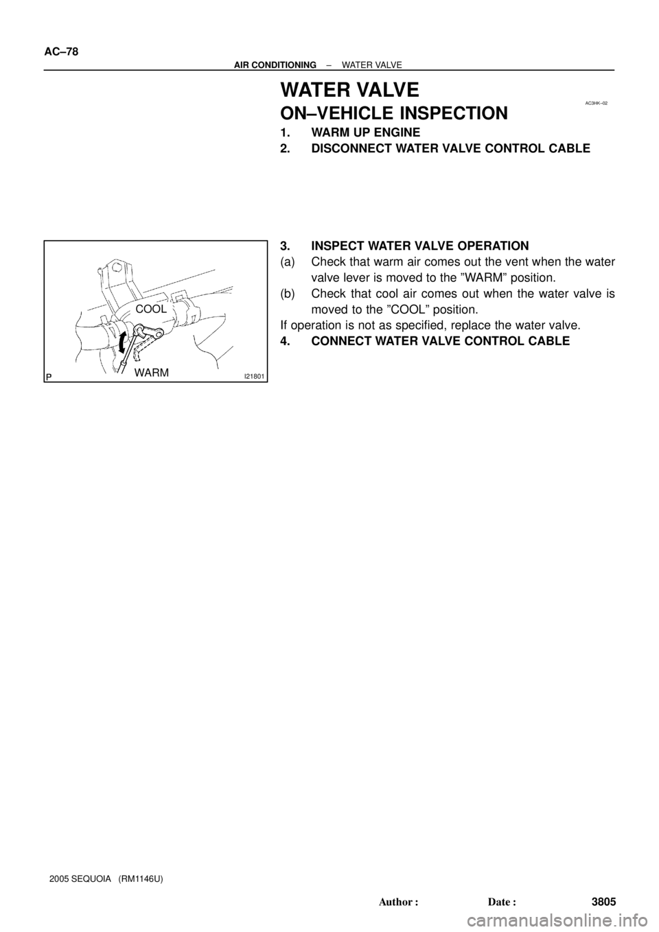
WATER VALVE
ON±VEHICLE INSPECTION
1. WARM UP ENGINE
2. DISCONNECT WATER VALVE CONTROL CABLE
3. INSPECT WATER VALVE OPERATION
(a) Check that warm air comes out the vent when the water
valve lever is moved to the ºWARMº position.
(b) Check that cool air comes out when the water valve is
moved to the ºCOOLº position.
If operation is not as specified, replace the water valve.
4. CONNECT WATER VALVE CONTROL CABLE
Page 3814 of 4323
AC3HL±02
I21369
I21370
I21371
± AIR CONDITIONINGWATER VALVE
AC±79
3806 Author�: Date�:
2005 SEQUOIA (RM1146U)
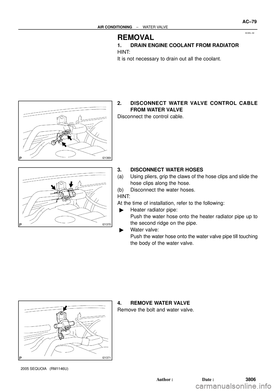
REMOVAL
1. DRAIN ENGINE COOLANT FROM RADIATOR
HINT:
It is not necessary to drain out all the coolant.
2. DISCONNECT WATER VALVE CONTROL CABLE
FROM WATER VALVE
Disconnect the control cable.
3. DISCONNECT WATER HOSES
(a) Using pliers, grip the claws of the hose clips and slide the
hose clips along the hose.
(b) Disconnect the water hoses.
HINT:
At the time of installation, refer to the following:
�Heater radiator pipe:
Push the water hose onto the heater radiator pipe up to
the second ridge on the pipe.
�Water valve:
Push the water hose onto the water valve pipe till touching
the body of the water valve.
4. REMOVE WATER VALVE
Remove the bolt and water valve.
Page 3827 of 4323

3,140 kpa 196 kpa
(2.0 kgf/cm
2, 28psi)
OFF (No Continuity)(32.0 kgf/cm2, 455psi)
OFF (No Continuity)
I05079
ON (Co")
I21455
2
13
4
AC1LS±03
Z13470
Low pressure High pressure
side side
ON (Continuity)
3,140 kpa 196 kpa
(2.0 kgf/cm
2, 28psi)
OFF (No Continuity)(32.0 kgf/cm2, 455psi)
OFF (No Continuity)
I05079
ON (Continuity)
1,520 kpa
1,230 kpa
(12.5 kgf/cm
2, 178psi) OFF (No Continuity)
(15.5 kgf/cm
2, 220psi) Cooling Fan Control AC±92
± AIR CONDITIONINGPRESSURE SWITCH
3819 Author�: Date�:
2005 SEQUOIA (RM1146U)
PRESSURE SWITCH
ON±VEHICLE INSPECTION
1. SET MANIFOLD GAUGE SET (See page AC±18)
2. DISCONNECT CONNECTOR
3. RUN ENGINE AT APPROX. 2,000 rpm
4. SET BLOWER SPEED CONTROL SWITCH TO ºHIº
POSITION
5. SET TEMPERATURE CONTROL LEVER TO ºMAX.
COOLº POSITION
6. A/C SWITCH ON
7. INSPECT PRESSURE SWITCH OPERATION
(a) Connect the positive (+) lead from the ohmmeter to termi-
nal 4 and the negative (±) lead to terminal 1.
(b) Check continuity between terminals when refrigerant
pressure is changed, as shown in the illustration.
If operation is not as specified, replace the pressure switch.
8. Cooling fan control:
INSPECT PRESSURE SWITCH OPERATION
9. STOP ENGINE AND REMOVE MANIFOLD GAUGE
SET
10. CONNECT CONNECTOR TO PRESSURE SWITCH
(a) Connect the positive (+) lead from the ohmmeter to termi-
nal 2 and the negative (±) lead to terminal 3.
(b) Check continuity between terminals when refrigerant
pressure is changed, as shown in the illustration.
If operation is not as specified, replace the pressure switch.
11. STOP ENGINE AND REMOVE MANIFOLD GAUGE
SET
12. CONNECT CONNECTOR TO PRESSURE SWITCH