Page 3738 of 4323

I21357
Sight Glass
AC1JT±06
± AIR CONDITIONINGAIR CONDITIONING SYSTEM
AC±3
3730 Author�: Date�:
2005 SEQUOIA (RM1146U)
ON±VEHICLE INSPECTION
1. INSPECT REFRIGERANT VOLUME
Observe the sight glass on the liquid tube.
Test conditions:
�Running engine at 1,500 rpm
�Single A/C:
Front blower speed control dial at ºHIº position
�Dual A/C:
Front and rear blower speed set at ºHIº position
�A/C switch ON
�Single A/C:
Front temperature control dial at ºMAX. COOLº position
�Dual A/C:
Front temperature control dial at ºMAX. COOLº position
Rear temperature control set at 18.5°C (65°F)
�Fully open the doors
ItemSymptomAmount of refrigerantRemedy
1Bubbles are present in sight glass continu-
ouslyInsufficient*
(1) Check for gas leakage with gas leak de-
tector and repair if necessary
(2) Add refrigerant until bubbles disappear
2No bubbles are present in sight glassNone, sufficient or too muchRefer to items 3 and 4
3No temperature difference between com-
pressor inlet and outletEmpty or nearly empty
(1) Check for gas leakage with gas leak de-
tector and repair if necessary
(2) Add refrigerant until bubbles disappear
4Temperature between compressor inlet and
outlet is noticeably differentCorrect or too muchRefer to items 5 and 6
5Immediately after air conditioning is turned
off, refrigerant in sight glass stays clearToo much
(1) Discharge refrigerant
(2) Evacuate air and charge proper amount
of purified refrigerant
6When air conditioning is turned off, refriger-
ant foams and then stays clearCorrect±
*: Bubbles in the sight glass with ambient temperature higher than usual can be considered normal if cooling
is sufficient.
Page 3739 of 4323
I21803
Single A/C:
Dual A/C: AC±4
± AIR CONDITIONINGAIR CONDITIONING SYSTEM
3731 Author�: Date�:
2005 SEQUOIA (RM1146U)
2. INSPECT REFRIGERANT PRESSURE WITH MAN-
IFOLD GAUGE SET
This is a method for checking the A/C system by using a man-
ifold gauge set. Read the manifold gauge pressure when the
conditions below are met.
Test conditions:
�Temperature at the air inlet with R/F switch set at RECIRC
is 30 to 35°C (86 to 95°F)
�Engine running at 1500 rpm
�Blower speed control switch at ºHIº position
�Temperature control dial at ºMAX. COOLº position
�Dual A/C:
Rear temperature control set at 18.5°C (65°F)
HINT:
Gauge indications may vary slightly due to ambient tempera-
ture conditions.
(1) Normally functioning refrigeration system.
Gauge reading:
Single A/C:
GaugeMPakgf´cm2
Low pressure0.15 to 0.251.5 to 2.5
High pressure1.6 to 1.816 to 18
Dual A/C:
GaugeMPakgf´cm2
Low pressure0.25 to 0.352.5 to 3.5
High pressure1.9 to 2.119 to 21
Page 3742 of 4323

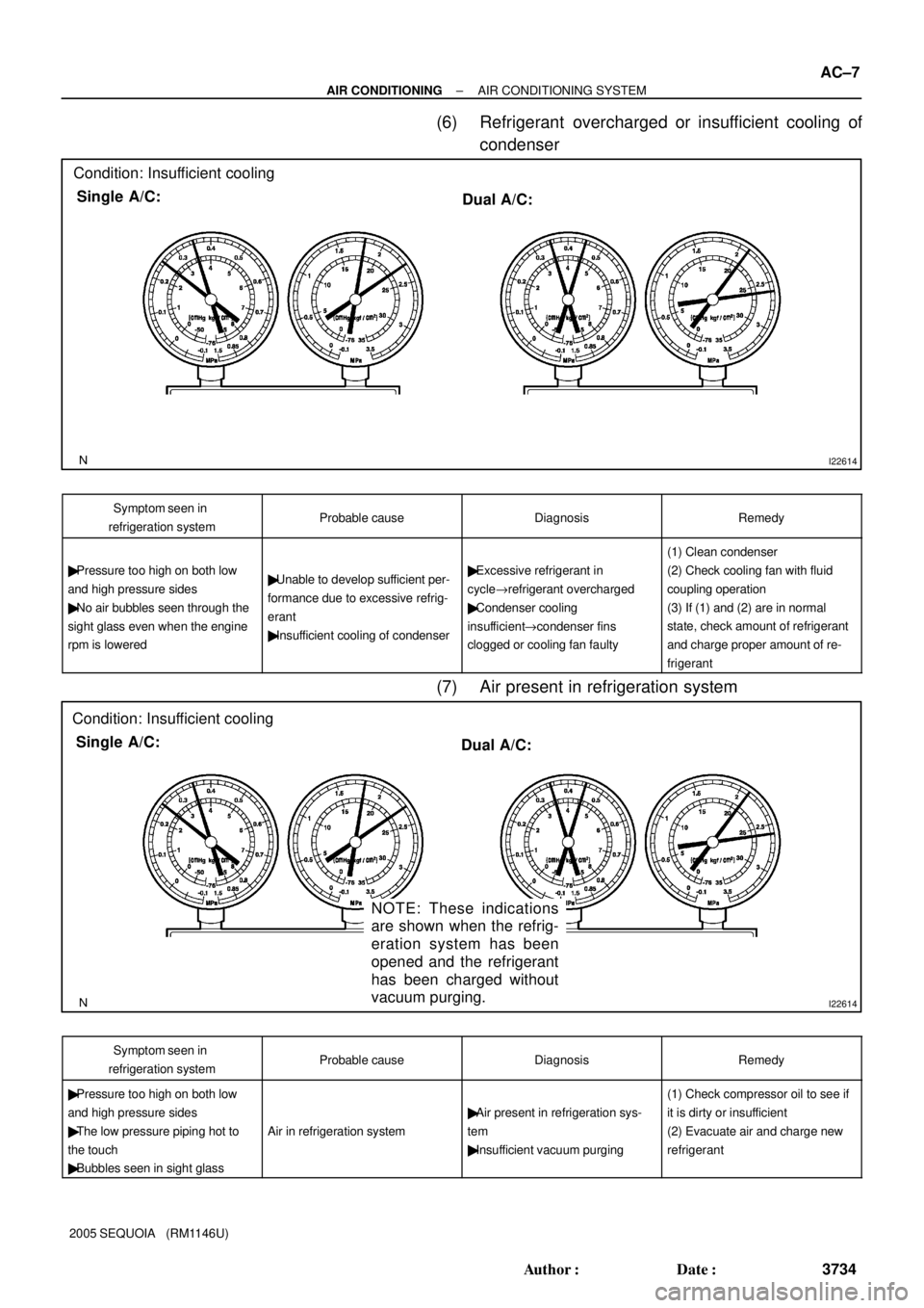
I22614
Condition: Insufficient cooling
Single A/C:
Dual A/C:
I22614
Condition: Insufficient cooling
Single A/C:
Dual A/C:
NOTE: These indications
are shown when the refrig-
eration system has been
opened and the refrigerant
has been charged without
vacuum purging.
± AIR CONDITIONINGAIR CONDITIONING SYSTEM
AC±7
3734 Author�: Date�:
2005 SEQUOIA (RM1146U)
(6) Refrigerant overcharged or insufficient cooling of
condenser
Symptom seen in
refrigeration systemProbable causeDiagnosisRemedy
� Pressure too high on both low
and high pressure sides
� No air bubbles seen through the
sight glass even when the engine
rpm is lowered� Unable to develop sufficient per-
formance due to excessive refrig-
erant
� Insufficient cooling of condenser� Excessive refrigerant in
cycle"refrigerant overcharged
� Condenser cooling
insufficient"condenser fins
clogged or cooling fan faulty
(1) Clean condenser
(2) Check cooling fan with fluid
coupling operation
(3) If (1) and (2) are in normal
state, check amount of refrigerant
and charge proper amount of re-
frigerant
(7) Air present in refrigeration system
Symptom seen in
refrigeration systemProbable causeDiagnosisRemedy
� Pressure too high on both low
and high pressure sides
� The low pressure piping hot to
the touch
� Bubbles seen in sight glass
Air in refrigeration system
� Air present in refrigeration sys-
tem
� Insufficient vacuum purging
(1) Check compressor oil to see if
it is dirty or insufficient
(2) Evacuate air and charge new
refrigerant
Page 3744 of 4323

± AIR CONDITIONINGAIR CONDITIONING SYSTEM
AC±9
3736 Author�: Date�:
2005 SEQUOIA (RM1146U)
3. INSPECT IDLE±UP SPEED
(a) Warm up the engine.
(b) Inspect idle±up speed when the following conditions are
established.
�Warm up engine
�Blower speed control switch at ºHIº position
�A/C switch ON
�Temperature control dial at ºCOOLº position
Magnetic clutch conditionIdle±up speed
Magnetic clutch not engaged700 ± 50 rpm
Magnetic clutch engaged780 ± 50 rpm
If idle speed is not as specified, check the Idle control system.
4. INSPECT FOR LEAKAGE OF REFRIGERANT
(a) Perform under the following conditions:
�Stop the engine.
�Secure good ventilation (If not, the gas leak detec-
tor may react to volatile gases witch are not refriger-
ant, such as evaporated gasoline and exhaust gas.)
�Repeat the test 2 or 3 times.
�Make sure that there is some refrigerant remaining
in the refrigeration system.
When the compressor is OFF: approx. 392 to 588
kPa (4 to 6 kgf/ cm
2, 57 to 85 psi)
(b) Bring the gas leak detector close to the drain hose before
performing the test.
HINT:
�After the blower motor stopped, leave the cooling unit for
more than 15 minutes.
�Bring the gas leak detector sensor under the drain hose.
�When bringing the gas leak detector close to the drain
hose, make sure that the gas leak detector does not react
to the volatile gases.
If such reaction is unavoidable, the vehicle must be lifted up.
(c) If gas leak is not detected on the drain hose, remove the
blower motor linear controller from the cooling unit. Then
insert the gas leak detector sensor into the unit and per-
form the test.
(d) Disconnect the connector and leave the pressure switch
for approx. 20 minutes. Then bring the gas leak detector
close to the pressure switch and perform the test.
(e) Bring the gas leak detector close to the refrigerant lines
and perform the test.
Page 3747 of 4323

N13790
Low Pressure
Service Valve
High Pressure
Service Valve
I21358
Properly
Charged
Insufficiently
Charged AC±12
± AIR CONDITIONINGAIR CONDITIONING SYSTEM
3739 Author�: Date�:
2005 SEQUOIA (RM1146U)
3. CHARGE REFRIGERANT INTO REFRIGERANT SYS-
TEM
If there is no leak after refrigerant leak check, charge the proper
amount of refrigerant into the refrigeration system.
CAUTION:
�Never run the engine when charging the system
through the high pressure side.
�Do not open the low pressure side valve when the
system is being charged with liquid refrigerant.
(a) Open the high pressure side valve fully.
(b) Charge specified amount of refrigerant, then close the
high pressure side valve.
HINT:
The system is fully charged if bubbles cannot be seen through
the sight glass.
(c) Partially charge the refrigeration system with refrigerant.
(1) Prepare the vehicle:
�Running engine at 1,500 rpm
�Single A/C:
Front blower speed control dial at ºHIº posi-
tion
�Dual A/C:
Front and rear blower speed set at ºHIº posi-
tion
�Single A/C:
Front temperature control dial at ºMAX.
COOLº position
�Dual A/C:
Front temperature control dial at ºMAX.
COOLº position
Rear temperature control set at 18.5°C
(65°F)
�Air inlet control set at ºRECIRCº
�Fully open doors (Sliding roof: closed)
(2) Open the low pressure side valve.
CAUTION:
Do not open the high pressure side valve.
(d) Charge refrigerant until bubbles disappear and check the
pressure on the gauge through the sight glass.
Page 3759 of 4323

AC3GV±02
I21372
I21373
AC±24
± AIR CONDITIONINGCOOLING UNIT
3751 Author�: Date�:
2005 SEQUOIA (RM1146U)
COOLING UNIT
ON±VEHICLE INSPECTION
1. INSPECT FOR LEAKAGE OF REFRIGERANT
(a) Remove the console box assembly.
(b) Remove the glove compartment door.
(c) Remove the lower No. 2 finish panel.
(d) Remove the heater to register duct No. 4.
(e) Remove the lower LH finish panel.
(f) Remove the lower cover (See page BO±89).
(g) Remove the blower controller.
(1) Disconnect the connector.
(2) Remove the 2 screws and blower motor linear con-
troller.
(h) Using a gas leak detector, check for leakage.
If there is leakage, check the tightening torque at the joints or
check the evaporator.
(i) Install the blower motor linear controller with the 2 screws.
(j) Install the lower cover.
(k) Install the lower LH finish panel.
(l) Install the lower No.2 finish panel.
(m) Install the glove compartment door (See page BO±97).
2. INSPECT EXPANSION VALVE
(a) Set the manifold gauge set.
(b) Run the engine.
(c) Check quantity of gas with the sight glass in refrigeration
cycle.
(1) Run the engine at 1,500 rpm for at least 5 minutes.
(2) Then check that the high pressure reading is 1.37
to 1.57 Mpa (14 to 16 kgm/cm
2, 199 to 228 psi).
(d) Check the expansion valve.
If the expansion valve is faulty, the low pressure reading will
drop to 0 kPa (0 kgf/cm
2, 0 psi).
HINT:
When the low pressure reading drops to 0 kPa (0 kgf/cm
2, 0
psi), there is no difference in temperature between the IN and
OUT sides of the receiver.
3. INSPECT THERMISTOR RESISTANCE
(a) Disconnect the connector.
(b) Measure the resistance between terminals.
Standard resistance: 1,500 W at 25°C (77°F)
If resistance is not as specified, replace the thermistor.
Page 3768 of 4323

AC3H3±02
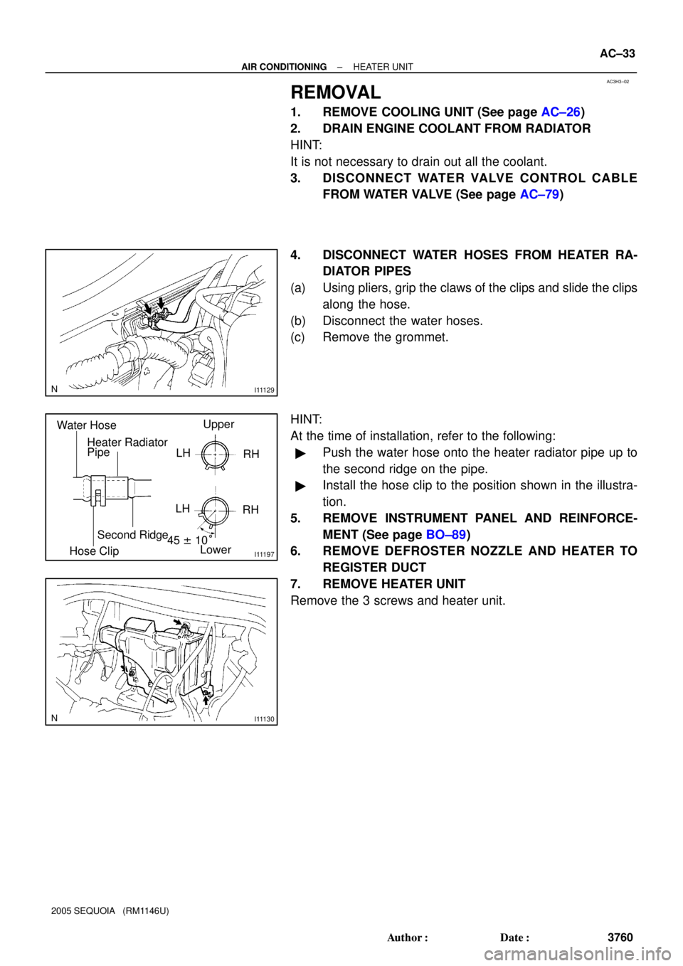
I11129
I11197
Water Hose
Heater Radiator
PipeUpper
LH
RH
45 ± 10°
Lower
Hose Clip
Second RidgeLH
RH
I11130
± AIR CONDITIONINGHEATER UNIT
AC±33
3760 Author�: Date�:
2005 SEQUOIA (RM1146U)
REMOVAL
1. REMOVE COOLING UNIT (See page AC±26)
2. DRAIN ENGINE COOLANT FROM RADIATOR
HINT:
It is not necessary to drain out all the coolant.
3. DISCONNECT WATER VALVE CONTROL CABLE
FROM WATER VALVE (See page AC±79)
4. DISCONNECT WATER HOSES FROM HEATER RA-
DIATOR PIPES
(a) Using pliers, grip the claws of the clips and slide the clips
along the hose.
(b) Disconnect the water hoses.
(c) Remove the grommet.
HINT:
At the time of installation, refer to the following:
�Push the water hose onto the heater radiator pipe up to
the second ridge on the pipe.
�Install the hose clip to the position shown in the illustra-
tion.
5. REMOVE INSTRUMENT PANEL AND REINFORCE-
MENT (See page BO±89)
6. REMOVE DEFROSTER NOZZLE AND HEATER TO
REGISTER DUCT
7. REMOVE HEATER UNIT
Remove the 3 screws and heater unit.
Page 3775 of 4323

AC3H9±02
I21380
I21381
AC±40
± AIR CONDITIONINGREAR A/C UNIT
3767 Author�: Date�:
2005 SEQUOIA (RM1146U)
REMOVAL
1. DISCHARGE REFRIGERANT FROM REFRIGERATION
SYSTEM
HINT:
At the time of installation, refer to the following item:
�Evacuate air from the refrigeration system.
�Charge the system with refrigerant and inspect for leak-
age of refrigerant.
Specified amount:
Dual A/C: 1050 ± 50 g (37.03 ± 1.76 oz.)
2. DRAIN ENGINE COOLANT FROM RADIATOR
HINT:
It is not necessary to drain out all coolant.
3. REMOVE REAR SEAT OUTER BELT FLOOR AN-
CHORS
4. REMOVE BACK DOOR SCUFF PLATE
5. REMOVE REAR DOOR SCUFF PLATE RH
6. REMOVE UPPER BACK DOOR GARNISH
7. REMOVE REAR WINDOW SIDE GARNISH RH
8. REMOVE REAR QUARTER TRIM PANEL RH
9. REMOVE QUARTER PILLAR GARNISH RH
10. DISCONNECT LIQUID AND SUCTION TUBES
Remove the 2 bolts and disconnect both tubes.
Torque: 5.4 N´m (55 kgf´cm, 48 in.´lbf)
NOTICE:
Cap the openings immediately to keep moisture or dirt out
of the system.
HINT:
At the time of installation, refer to the following:
Lubricate 2 new O±rings with compressor oil and install them
to the tubes.
11. DISCONNECT WATER HOSES FROM HEATER PIPES
(a) Grip the claws of the hose clip and slide the hose clip
along the hose.
(b) Disconnect the water hoses.