Page 3040 of 4323

INSTALLATION
1. INSTALL DRIVE SHAFT TO DIFFERENTIAL
(a) Install a new snap ring to the inboard jo")
SA14I±10
SA±36
± SUSPENSION AND AXLEFRONT DRIVE SHAFT
3032 Author�: Date�:
2005 SEQUOIA (RM1146U)
INSTALLATION
1. INSTALL DRIVE SHAFT TO DIFFERENTIAL
(a) Install a new snap ring to the inboard joint shaft.
(b) Apply gear oil to the inboard joint shaft and differential case sliding surface.
(c) Set the snap ring with opening side facing downward.
(d) Using a brass bar and hammer, install the drive shaft.
NOTICE:
Be careful not to damage the dust cover and oil seal.
HINT:
Whether the inboard joint shaft is in contact with the pinion shaft or not can be known from the sound or feel-
ing when driving.
(e) Check that there is 2 ± 3 mm (0.08 ± 0.12 in.) of play in the axial direction.
(f) Check that the drive shaft cannot be removed by hand.
2. LH drive shaft:
INSTALL LH SHOCK ABSORBER (See page SA±70)
3. CONNECT DRIVE SHAFT TO STEERING KNUCKLE
NOTICE:
Be careful not to damage the oil seal, boots and dust seal.
4. CONNECT LOWER SUSPENSION ARM TO LOWER BALL JOINT
(a) Connect the lower suspension arm to the lower ball joint.
(b) Install the nut and a new cotter pin.
If the holes for the cotter pin are not aligned, tighten the nut further up to 60°.
HINT:
Face the hole for the cotter pin forward.
Torque: 140 N´m (1,450 kgf´cm, 103 ft´lbf)
5. INSTALL DRIVE SHAFT LOCK NUT
(a) While applying brakes, install the nut.
Torque: 235 N´m (2,400 kgf´cm, 173 ft´lbf)
(b) Install the lock cap and a new cotter pin.
If the holes for the cotter pin are not aligned, tighten the nut further up to 60°.
6. FILL DIFFERENTIAL WITH HYPOID GEAR OIL (See page SA±38)
7. INSTALL ENGINE UNDER COVER
8. INSTALL FRONT WHEEL
Torque: 110 N´m (1,150 kgf´cm, 83 ft´lbf)
Page 3042 of 4323
SA23L±04
Z00638
SST
R13369
SST
R13370
SST
R13371
SST SA±38
± SUSPENSION AND AXLEFRONT DIFFERENTIAL REAR OIL SEAL
3034 Author�: Date�:
2005 SEQUOIA (RM1146U)
REPLACEMENT
1. REMOVE ENGINE UNDER COVER
2. DRAIN DIFFERENTIAL OIL
3. REMOVE FRONT PROPELLER SHAFT
(See page PR±7)
4. REMOVE COMPANION FLANGE
(a) Using a chisel and hammer, loosen the staked part of the
nut.
(b) Using SST to hold the flange, remove the nut.
SST 09330±00021
(c) Using SST, remove the companion flange.
SST 09950±30012 (09951±03010, 09953±03010,
09954±03010, 09955±03030, 09956±03020)
5. REMOVE OIL SEAL AND OIL SLINGER
(a) Using SST, remove the oil seal.
SST 09308±10010
(b) Remove the oil slinger.
6. REMOVE REAR BEARING AND BEARING SPACER
(a) Using SST, remove the rear bearing from the drive pinion.
SST 09556±22010
(b) Remove the bearing spacer.
7. INSTALL BEARING SPACER, REAR BEARING AND
OIL SLINGER
(a) Install a new bearing spacer and place the rear bearing
and oil slinger.
Page 3043 of 4323

FA1083
SST
FA1084
R13338
Less than
5 mm (0.20 in.)
± SUSPENSION AND AXLEFRONT DIFFERENTIAL REAR OIL SEAL
SA±39
3035 Author�: Date�:
2005 SE")
R13368
SST
R13374
SST
4.5 ± 0.3 mm
(0.177 ± 0.012 in.)
FA1083
SST
FA1084
R13338
Less than
5 mm (0.20 in.)
± SUSPENSION AND AXLEFRONT DIFFERENTIAL REAR OIL SEAL
SA±39
3035 Author�: Date�:
2005 SEQUOIA (RM1146U)
(b) Using SST and the companion flange, install the rear
bearing, then remove the companion flange.
SST 09950±30012 (09951±03010, 09953±03010,
09954±03010, 09955±03030, 09956±03020)
8. INSTALL OIL SEAL
(a) Coat a new oil seal lip with MP grease.
(b) Using SST and a hammer, install the oil seal.
SST 09554±22010
Oil seal drive in depth: 4.5 ± 0.3 mm (0.177 ± 0.012 in.)
9. INSTALL COMPANION FLANGE
(a) Place the companion flange on the drive pinion.
(b) Coat the threads of a new nut with hypoid gear oil.
(c) Using SST to hold the flange, torque the nut.
SST 09330±00021
Torque: 108 N´m (1,100 kgf´cm, 80 ft´lbf)
10. ADJUST DRIVE PINION PRELOAD
(See page SA±50)
11. STAKE DRIVE PINION NUT
12. INSTALL FRONT PROPELLER SHAFT
(See page PR±9)
13. FILL DIFFERENTIAL WITH HYPOID GEAR OIL
Torque: 39 N´m (400 kgf´cm, 29 ft´lbf)
Oil type: Hypoid gear oil API GL±5
Recommended oil viscosity: SAE 75W±90
Capacity: 1.15 liters (1.22 US qts, 1.01 Imp. qts)
14. INSTALL ENGINE UNDER COVER
Page 3136 of 4323

HINT:
Perform the following before")
F16839
Do not extend
the rear pneumatic
cylinder
Hole
Seating Pin SA±132
± SUSPENSION AND AXLEREAR PNEUMATIC CYLINDER
3128 Author�: Date�:
2005 SEQUOIA (RM1146U)
HINT:
Perform the following before installation.
When using safety stands and jack:
(1) Jack up the rear axle until the bottom of the rear
pneumatic cylinder touches the rear axle and fit the
seating pin on the lower side of the rear pneumatic
cylinder into the rear axle.
NOTICE:
�Do not extend the rear pneumatic cylinder in order to
fit the seating pin into the hole.
�Make sure that the seating pin on the lower side of the
rear pneumatic cylinder fits in the hole in the rear
axle.
(2) Remove the safety stands with care not to extend
the rear pneumatic cylinder when jacking down the
vehicle till it sits on the ground.
NOTICE:
Make sure that the diaphragm (rubber part) of the pneumat-
ic cylinder is not deformed.
(3) Start the engine and replenish the rear pneumatic
cylinder with air.
(e) When using a swing arm type lift:
(1) Lower the vehicle till the tires hit the ground, and
continue lowering slowly until the bottom of the rear
pneumatic cylinder touches the rear axle.
(2) Align the seating pin on the cylinder with the hole in
the rear axle and install the rear pneumatic cylinder
on the rear axle.
NOTICE:
�Do not extend the rear pneumatic cylinder by lifting
up the rear axle housing after fitting the seating pin.
�Make sure that the diaphragm (rubber part) of the
pneumatic cylinder is not deformed.
(3) Lower the lift carefully so as not to extend the rear
pneumatic cylinder.
NOTICE:
Make sure that the diaphragm (rubber part) of the pneumat-
ic cylinder is not deformed.
(4) Start the engine and replenish the rear pneumatic
cylinder with air.
Page 3160 of 4323

ADJUSTMENT
1. ADJUST STANDARD VEHICLE HEIGHT
(a) Releas")
SA2D0±01
F16824
HIGH
NORMAL
LOW SA±156
± SUSPENSION AND AXLEELECTRONIC MODULATED AIR SUSPENSION
3152 Author�: Date�:
2005 SEQUOIA (RM1146U)
ADJUSTMENT
1. ADJUST STANDARD VEHICLE HEIGHT
(a) Release the parking brake and stabilize the suspensions by pushing up and down on the corners of
the vehicle.
(b) Place the shift lever into the ºNº position and settle the tires by moving the vehicle back and forth.
(c) Start the engine.
(d) On the height control switch, first press ºHIGHº to raise the vehicle height, and then change the switch
to ºLOWº to lower it. Perform this operation one more time.
NOTICE:
Make sure to release the parking brake and move the shift lever into the ºNº position.
2. INSPECT TIRE (See page SA±3)
3. MEASURE VEHICLE HEIGHT (See page SA±4)
4. OPERATE HEIGHT CONTROL SWITCH AND CHECK
VEHICLE HEIGHT CHANGE
(a) Start the engine and change the height control switch
from the NORMAL position to the HIGH and LOW posi-
tions.
Check the time until the height adjustment is completed
and the amount of change in vehicle height.
Adjustment time
From operation of height control switch
to start of compressor.Approx. 2 sec.
From start of compressor to completion
of height adjustment.Approx. 20 sec.
Amount of change in vehicle height
HIGH position: 40 mm (1.57 in.)
LOW position:
4WD models: ±30 mm (±1.18 in.)
2WD models: ±15 mm (±0.59 in.)
Page 3161 of 4323
F19820
HIGH
NORMAL
LOW
± SUSPENSION AND AXLEELECTRONIC MODULATED AIR SUSPENSION
SA±157
3153 Author�: Date�:
2005 SEQUOIA (RM1146U)
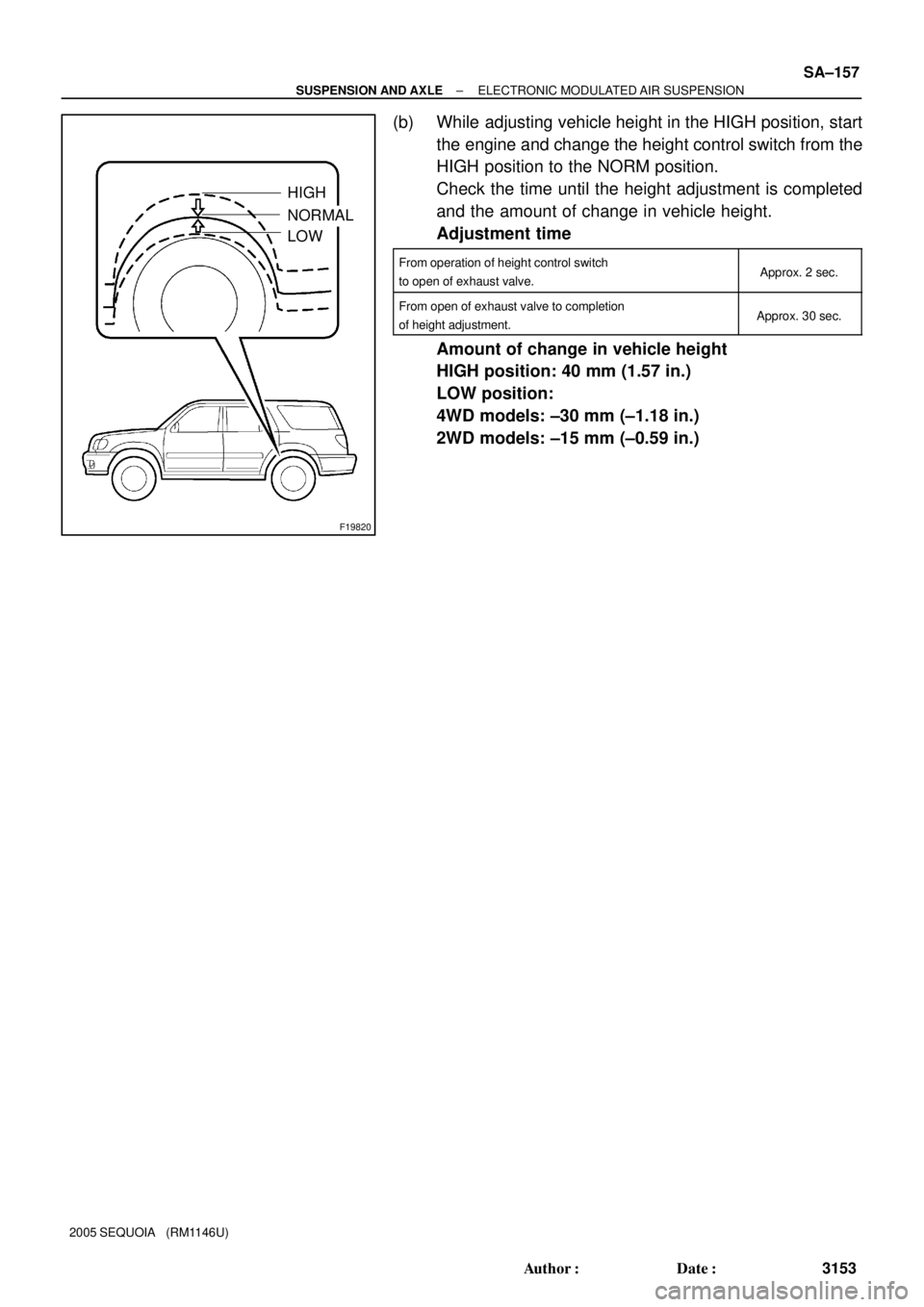
(b) While adjusting vehicle height in the HIGH position, start
the engine and change the height control switch from the
HIGH position to the NORM position.
Check the time until the height adjustment is completed
and the amount of change in vehicle height.
Adjustment time
From operation of height control switch
to open of exhaust valve.Approx. 2 sec.
From open of exhaust valve to completion
of height adjustment.Approx. 30 sec.
Amount of change in vehicle height
HIGH position: 40 mm (1.57 in.)
LOW position:
4WD models: ±30 mm (±1.18 in.)
2WD models: ±15 mm (±0.59 in.)
Page 3162 of 4323
F16825
Front SA±158
± SUSPENSION AND AXLEELECTRONIC MODULATED AIR SUSPENSION
3154 Author�: Date�:
2005 SEQUOIA (RM1146U)
5. CHECK CONNECTIONS OF TUBES FOR AIR LEAK-
AGE
(a) Set the height control switch in the HIGH position and
raise the vehicle height.
(b) Stop the engine.
(c) Apply soapy water to the connections of the tubes and
check if there is any air leakage.
6. ADJUST VEHICLE HEIGHT
NOTICE:
While adjusting vehicle height, do not put anyone or any-
thing on or in the vehicle as it will affect vehicle height.
(a) Suspend the vehicle height control by pressing the height
control mode select switch.
(b) Put the vehicle on a level surface.
Page 3181 of 4323

BRAKE PEDAL
ON±VEHICLE INSPECTION
1. CHECK PEDAL HEIGHT
Pedal hei")
F07754
Pedal Height Push Rod
BR107±04
R00085
Pedal Free Play BR±6
± BRAKEBRAKE PEDAL
3173 Author�: Date�:
2005 SEQUOIA (RM1146U)
BRAKE PEDAL
ON±VEHICLE INSPECTION
1. CHECK PEDAL HEIGHT
Pedal height from dash panel:
151.1 ± 165.1 mm (5.949 ± 6.500 in.)
NOTICE:
Do not adjust the pedal height. Doing so by changing the
push rod length of the brake booster will structurally
change the pedal ratio.
If the pedal height is incorrect, check that there is no damage
in brake pedal, brake pedal lever, brake pedal bracket and dash
panel.
�Even if there is damage, there is no problem if the
reserve distance is within the standard value.
�If necessary, replace them.
2. IF NECESSARY, ADJUST STOP LIGHT SWITCH
(a) Remove the front door scuff plate, cowl side trim, side
panel, lower finish panel and No. 2 heater to register duct
(See page BO±89).
(b) Loosen the stop light switch lock nut.
(c) Push the brake pedal in 5 ± 15 mm (0.20 ± 0.59 in.), turn
the stop light switch to lock the nut in the position where
the stop light goes off.
(d) Push the brake pedal in 5 ±15 mm (0.20 ± 0.59 in.), check
that the stop light lights up.
(e) Install the No. 2 heater to register duct, lower finish panel,
side panel, cowl side trim and front door scuff plate (See
page BO±89).
3. CHECK PEDAL FREE PLAY
(a) Stop the engine and depress the brake pedal several
times until there is no more vacuum left in the booster.
(b) Push in the pedal by hand until the second point of resis-
tance begins to be felt, then measure the distance as
shown in the illustration.
Pedal free play: 1 ± 6 mm (0.04 ± 0.24 in.)
HINT:
The free play to the first point of resistance is due to the play
between the clevis and pin. It is 1 ± 3 mm (0.04 ± 0.12 in.) at the
pedal.
If incorrect, check the stop light switch clearance. If the clear-
ance is OK, then troubleshoot the brake system.
Stop light switch clearance:
0.5 ± 2.4 mm (0.020 ± 0.095 in.)