Page 2679 of 4323

2671 Author�: Date�:
2005 SEQUOIA (RM1146U)
REMOVAL
1. REMOVE FRONT EXHAUST PIPES
(See page EM±126)
2. REMOVE FRONT AND REAR PROPELLER SHAFTS")
EM11X±07
EM±92
± ENGINE MECHANICALENGINE UNIT (4WD)
2671 Author�: Date�:
2005 SEQUOIA (RM1146U)
REMOVAL
1. REMOVE FRONT EXHAUST PIPES
(See page EM±126)
2. REMOVE FRONT AND REAR PROPELLER SHAFTS
(See page PR±7)
3. REMOVE FRONT STABILIZER BAR
(See page SA±91)
4. REMOVE TRANSMISSION (See page AT±25)
5. REMOVE ENGINE HOOD
6. REMOVE ENGINE UNDER COVER
7. DISCONNECT BATTERY CABLES
(a) Disconnect the clamp on battery negative (±) cable from
the No.2 relay box.
(b) Disconnect the battery positive (+) terminal cable.
(c) Disconnect the battery negative (±) cable from the left
fender apron.
8. DRAIN ENGINE COOLANT
9. REMOVE RADIATOR ASSEMBLY (See page CO±17)
10. REMOVE THROTTLE BODY COVER
11. REMOVE AIR CLEANER AND INTAKE AIR CONNEC-
TOR ASSEMBLY
(a) Disconnect the MAF meter connector.
(b) Loosen the 3 bolts, and remove the air cleaner case.
(c) Remove the suction hose from the intake air connector.
(d) Disconnect the PS air hose, air inlet hose for EVAP, PCV
hose and MAF meter wire from the air intake connector.
(e) Disconnect the intake air connector from the throttle body.
12. REMOVE DRIVE BELT, FAN, FLUID COUPLING AND
FAN PULLEY
(a) Loosen the 4 nuts holding the fluid coupling to the fan
bracket.
(b) Remove the drive belt. (See page CH±16)
(c) Remove the 4 nuts, the fan, fluid coupling assembly and
fan pulley.
13. DISCONNECT ENGINE WIRE FROM CABIN
(a) Remove the glove compartment door.
(b) Remove the lower No.2 panel.
(c) Remove the 3 screws, and disconnect the ECM from the
body bracket.
(d) Disconnect the 3 wire harness connectors from the ECM.
(e) Disconnect the 2 wire harness connectors (cassette con-
nector).
Page 2680 of 4323

EM±93
2672 Author�: Date�:
2005 SEQUOIA (RM1146U)
(f) Disconnect the engine wire from the engine wire bracket
and remov")
B07536
Disconnect
A08905
A08907
A08936
± ENGINE MECHANICALENGINE UNIT (4WD)
EM±93
2672 Author�: Date�:
2005 SEQUOIA (RM1146U)
(f) Disconnect the engine wire from the engine wire bracket
and remove the 2 nuts, bolt and bracket.
(g) Pull out the engine wire from the cowl panel.
14. DISCONNECT HOSES, WIRES, CONNECTORS,
CLAMPS, GROMMET AND CABLES
(a) Disconnect the 2 PS air hoses from hose clamp on the
No.3 RH timing belt cover.
(b) Disconnect the generator wire.
(c) Disconnect the generator connector.
(d) Disconnect the hose clamp for the PS air hose.
(e) Disconnect the PS air hose from the upper intake man-
ifold.
(f) Disconnect the 2 heater hoses.
(g) Disconnect the ground strap from the cowl panel.
(h) Disconnect the fuel inlet hose and clamps.
(i) Disconnect the fuel return hose and clamp.
(j) Disconnect the air inlet hose from the charcoal canister.
(k) Disconnect the EVAP hose from the charcoal canister.
(l) Disconnect the brake booster tube.
15. DISCONNECT A/C COMPRESSOR FROM ENGINE
(a) Disconnect the A/C compressor connector.
(b) Remove the 3 bolts, and disconnect the A/C compressor
from the engine.
HINT:
Suspend the A/C compressor securely.
16. DISCONNECT PS PUMP FROM ENGINE
Remove the 3 bolts, and disconnect the PS pump from the en-
gine.
HINT:
Suspend the PS pump securely.
17. REMOVE OIL COOLER PIPES FOR TRANSMISSION
(a) Remove the 3 bolts and 3 stays.
(b) Loosen the 2 union nuts, and remove the 2 oil cooler
pipes.
18. REMOVE ENGINE ASSEMBLY FROM VEHICLE
(a) Attach the engine chain hoist to the engine hangers.
(b) Remove the 4 bolts holding the engine mounting brackets
to the frame brackets.
Page 2681 of 4323
A08932
Lift
A04857
EM±94
± ENGINE MECHANICALENGINE UNIT (4WD)
2673 Author�: Date�:
2005 SEQUOIA (RM1146U)
(c) Lift the engine out of the vehicle slowly and carefully.
HINT:
Make sure the engine is clear of all wiring, hoses and cables.
(d) Place the engine and transmission assembly onto the
stand.
19. REMOVE DRIVE PLATE
Remove the 8 bolts, front spacer, drive plate and rear spacer.
Page 2682 of 4323

EM±95
2674 Author�: Date�:
2005 SEQUOIA (RM1146U)
INSTALLATION
1. IN")
EM11Y±07
A04869
Adhesive
A04857
1
2
3
47
6
8
5
A05137
Painted
Mark
90°
90°
A08933
Lower
± ENGINE MECHANICALENGINE UNIT (4WD)
EM±95
2674 Author�: Date�:
2005 SEQUOIA (RM1146U)
INSTALLATION
1. INSTALL DRIVE PLATE
HINT:
�The mounting bolts are tightened in 2 progressive steps
(steps (c) and (e)).
�If any one of the mounting bolts is broken or deformed, re-
place it.
(a) Apply adhesive to 2 or 3 threads of the mounting bolt end.
Adhesive:
Part No. 08833±00070, THREE BOND 1324 or equiva-
lent
(b) Install the front spacer, drive plate and rear spacer on the
crankshaft.
(c) Install and uniformly tighten the 8 mounting bolts in sever-
al passes, in the sequence shown.
Torque: 49 N´m (500 kgf´cm, 36 ft´lbf)
If any one of the mounting bolts does not meet the torque speci-
fication, replace the mounting bolt.
(d) Mark the mounting bolt with paint.
(e) Retighten the mounting bolts by 90° in the numerical or-
der shown.
(f) Check that the painted mark is now at a 90° angle to (e).
2. INSTALL ENGINE ASSEMBLY IN VEHICLE
(a) Attach the engine chain hoist to the engine hangers.
(b) Slowly lower the engine assembly into the engine
compartment.
(c) Attach the engine mounting brackets to the frame brack-
ets.
Page 2683 of 4323

2675 Author�: Date�:
2005 SEQUOIA (RM1146U)
(d) Install the engine mounting brackets to the frame brack-
ets with the 2 nuts and 4 b")
A08936
A08907
A08905
EM±96
± ENGINE MECHANICALENGINE UNIT (4WD)
2675 Author�: Date�:
2005 SEQUOIA (RM1146U)
(d) Install the engine mounting brackets to the frame brack-
ets with the 2 nuts and 4 bolts.
Torque: 38 N´m (388 kgf´cm, 28 ft´lbf)
(e) Remove the engine chain hoist.
3. INSTALL PS PUMP
Install the PS pump with the 3 bolts.
Torque: 17 N´m (175 kgf´cm, 13 ft´lbf)
4. INSTALL A/C COMPRESSOR
(a) Install the A/C compressor with the 3 bolts.
Torque: 49 N´m (500 kgf´cm, 36 ft´lbf)
(b) Connect the A/C compressor connector.
5. CONNECT HOSES, WIRES, CONNECTORS, CLAMPS,
GROMMET AND CABLES
(a) Connect the 2 PS air hoses to hose clamp on the No.3 RH
timing belt cover.
(b) Connect the generator wire.
(c) Connect the generator connector.
(d) Connect the hose clamp for the PS air hose.
(e) Connect the PS air hose to the upper intake manifold.
(f) Connect the 2 heater hoses.
(g) Connect the ground strap to the cowl panel.
(h) Connect the fuel inlet hose and clamps.
(i) Connect the fuel return hose and clamp.
(j) Connect the air inlet hose to the charcoal canister.
(k) Connect the EVAP hose to the charcoal canister.
(l) Connect the brake booster tube.
6. CONNECT ENGINE WIRE TO CABIN
(a) Push into the engine wire through the cowl panel.
Page 2684 of 4323

EM±97
2676 Author�: Date�:
2005 SEQUOIA (RM1146U)
(b) Install the engine wire bracket with the 2 nuts and bolt and
connect the engine wire to t")
A09152
Connect
± ENGINE MECHANICALENGINE UNIT (4WD)
EM±97
2676 Author�: Date�:
2005 SEQUOIA (RM1146U)
(b) Install the engine wire bracket with the 2 nuts and bolt and
connect the engine wire to the bracket.
(c) Connect the 3 connectors to the ECM.
(d) Connect the 2 wire harness connectors (cassette con-
nector).
(e) Install the ECM with the 3 screws.
(f) Install the lower No.2 panel.
(g) Install the glove compartment door.
7. INSTALL FAN PULLEY, FAN, FLUID COUPLING AND
DRIVE BELT
(a) Temporarily install the fan pulley, the fan and fluid cou-
pling assembly with the 4 nuts.
(b) Install the drive belt. (See page CH±16)
(c) Tighten the 4 nuts holding the fluid coupling to the fan
bracket.
8. INSTALL AIR CLEANER AND INTAKE AIR CONNEC-
TOR PIPE ASSEMBLY
(a) Install the air cleaner case with the 3 bolts.
Torque: 5.0 N´m (51 kgf´cm, 44 in.´lbf)
(b) Connect the intake air connector to the throttle body.
(c) Connect the MAF meter connector.
(d) Install the suction hose to the intake air connector.
(e) Connect the PS air hose, air inlet hose for EVAP, PCV
hose and MAF meter connector to the intake air connec-
tor.
9. INSTALL THROTTLE BODY COVER
10. INSTALL TRANSMISSION (See page AT±29)
11. INSTALL RADIATOR ASSEMBLY (See page CO±18)
12. INSTALL FRONT STABILIZER BAR
(See page SA±93)
13. INSTALL FRONT AND REAR PROPELLER SHAFTS
(See page PR±9)
14. INSTALL FRONT EXHAUST PIPES
(See page EM±126)
15. INSTALL BATTERY CABLES
(a) Connect the battery positive (+) terminal cable.
(b) Connect the battery negative (±) cable to the battery and
left fender apron.
(c) Connect the clamp on battery negative (±) cable to No.2
relay box.
16. PERFORM INITIALIZATION
Some system need initialzation when disconnecting the cable
from the battery terminal.
17. FILL WITH ENGINE COOLANT (See page CO±2)
18. FILL WITH ENGINE OIL (See page LU±2)
19. START ENGINE AND CHECK FOR LEAKS
20. INSTALL ENGINE UNDER COVERS
21. INSTALL HOOD
Page 2685 of 4323
EM±98
± ENGINE MECHANICALENGINE UNIT (4WD)
2677 Author�: Date�:
2005 SEQUOIA (RM1146U)
22. PERFORM ROAD TEST
Check for abnormal noise, shock, slippage, correct shift points
and smooth operation.
23. RECHECK ENGINE COOLANT AND OIL LEVELS
Page 2686 of 4323
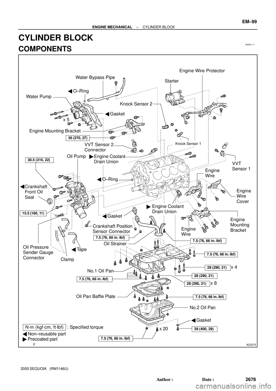
EM0E9±17
A23375
Engine Mounting Bracket
Oil Pump
Crankshaft
Front Oil
Seal
Crankshaft Position
Sensor Connector
No.1 Oil Pan
� Non±reusable part
� Precoated partOil StrainerEngine
Mounting
Bracket
VVT Sensor 2
ConnectorKnock Sensor 1
Knock Sensor 2
Engine Coolant
Drain UnionStarter
No.2 Oil Pan Oil Pan Baffle Platex 8 Water Pump
� Gasket � O±Ring
Engine
Wire
Engine
Wire
Cover VVT
Sensor 1
Engine Coolant
Drain Union
36 (370, 27)
30.5 (310, 22)
x 5
Oil Pressure
Sender Gauge
Connector
7.5 (76, 66 in.´lbf)
7.5 (76, 66 in.´lbf)
7.5 (76, 66 in.´lbf)
N´m (kgf´cm, ft´lbf) : Specified torque �
�
x 20
Clamp
Engine Wire Protector
� Tape
28 (290, 21)
7.5 (76, 66 in.´lbf)
28 (290, 21)
Water Bypass Pipe
7.5 (76, 66 in.´lbf)
� O±Ring
� Gasket
Engine
Wire
15.5 (160, 11)
39 (400, 29)
� Gasket
�
28 (290, 21)
7.5 (76, 66 in.´lbf)
x 4
± ENGINE MECHANICALCYLINDER BLOCK
EM±99
2678 Author�: Date�:
2005 SEQUOIA (RM1146U)
CYLINDER BLOCK
COMPONENTS