Page 2655 of 4323

(7) Apply seal packing to the front bearing cap.
�Remove")
A16832
Seal Packing
Seal Width
1.5 mm
A23360
A23361
Push EM±68
± ENGINE MECHANICALCYLINDER HEAD
2647 Author�: Date�:
2005 SEQUOIA (RM1146U)
(7) Apply seal packing to the front bearing cap.
�Remove any old packing material (FIPG) and
be careful not to drop any oil on the contact
surfaces of the bearing cap and cylinder
head.
Using a razor blade and gasket scraper, re-
move all the old packing material (FIPG) from
the gasket surfaces and groove.
Thoroughly clean all components to remove
all the loose material.
Using a non±residue solvent, clean both
sealing surfaces.
�Apply seal packing to the bearing cap as
shown in the illustration.
Install a nozzle that has been cut to a 1.5 mm
(0.059 in.) opening.
Parts must be assembled within 5 minutes of
application. Otherwise the material must be
removed and reapplied.
Immediately remove the nozzle from the tube
and reinstall cap.
Seal packing: Part No. 08826±00080 or equivalent
NOTICE:
Do not apply seal packing to the front bearing cap grooves.
(8) Install the front bearing cap.
HINT:
Installing the front bearing cap will determine the thrust portion
of the camshaft.
(9) Install the other bearing caps in the sequence
shown with the arrow mark facing forward.
(10) Push in the camshaft oil seal.
Page 2656 of 4323

A23340
A
B
C
E
EA
B C
EE
E
EE
EE D
E EEE
ED
A23340
1
4
22
82
3 21
6
57
13 141912
11
15
1620
9
1017
18
A23338
Service Bolt
EM7143
Seal Packing
± ENGINE MECHANICALCYLINDER HEAD
EM±69
2648 Author�: Date�:
2005 SEQUOIA (RM1146U)
(11) Install 4 new seal washers to the bearing cap bolts
(A and B).
(12) Apply a light coat of engine oil on the threads and
under the heads of the bearing cap bolts (D and E).
NOTICE:
Do not apply engine oil under the heads of the bearing cap
bolts (A), (B) and (C).
HINT:
Each bolt length is indicated in the illustration.
Bolt length:
94 mm (3.70 in.) for A with seal washer
72 mm (2.83 in.) for B with seal washer
25 mm (0.98 in.) for C
52 mm (2.05 in.) for D
38 mm (1.50 in.) for E
(13) Install the oil feed pipe and the 22 bearing cap bolts
as shown in the illustration.
(14) Uniformly tighten the 22 bearing cap bolts in several
steps, in the sequence shown.
Torque:
7.5 N´m (76 kgf´cm, 66 in.´lbf) for bolt C
16 N´m (160 kgf´cm, 12 ft´lbf) for others
(15) Remove the service bolt.
9. CHECK AND ADJUST VALVE CLEARANCE
(See page EM±4)
Turn the camshaft so that the cam lobe faces upward, and
check and adjust the valve clearance.
10. INSTALL CAMSHAFT TIMING OIL CONTROL VALVE
(See page SF±48)
11. INSTALL SEMI±CIRCULAR PLUGS
(a) Remove any old packing material (FIPG).
(b) Apply seal packing to the semi±circular plug grooves.
Seal packing:
Part No. 08826±00080 or equivalent
Page 2657 of 4323
A23362
RH Bank
LH Bank
A23363: Seal Packing
A14369
A23364: Seal Packing
EM±70
± ENGINE MECHANICALCYLINDER HEAD
2649 Author�: Date�:
2005 SEQUOIA (RM1146U)
(c) Install the 4 semi±circular plugs to the cylinder heads as
shown in the illustration.
12. INSTALL LH CYLINDER HEAD COVER
(a) Remove any old packing material (FIPG).
(b) Apply seal packing to the cylinder heads as shown in the
illustration.
Seal packing: Part No. 08826±00080 or equivalent
(c) Install the gasket to the cylinder head cover.
(d) Install the seal washer to the bolt.
(e) Install the cylinder head cover with the 9 bolts. Uniformly
tighten the bolts in several steps.
Torque: 6.0 N´m (60 kgf´cm, 53 in.´lbf)
13. INSTALL RH CYLINDER HEAD COVER
(a) Remove any old packing material (FIPG).
(b) Apply seal packing to the cylinder heads as shown in the
illustration.
Seal packing: Part No. 08826±00080 or equivalent
Page 2658 of 4323

(c) Install the")
A04015
Wire
Clamp
Bracket
A23333
Rear Water Bypass Joint
A23332
Front Water Bypass Joint
A23331
± ENGINE MECHANICALCYLINDER HEAD
EM±71
2650 Author�: Date�:
2005 SEQUOIA (RM1146U)
(c) Install the gasket to the cylinder head cover.
(d) Install the seal washer to the bolt.
(e) Install the cylinder head cover with the 9 bolts. Uniformly
tighten the bolts in several steps. Install the 2 cylinder
head covers.
Torque: 6.0 N´m (60 kgf´cm, 53 in.´lbf)
(f) Install the wire clamp bracket on the engine wire to the
camshaft bearing cap.
14. INSTALL ENGINE HANGERS
Torque: 37 N´m (380 kgf´cm, 27 ft´lbf)
15. INSTALL VVT SENSORS (See page SF±77)
16. INSTALL OIL DIPSTICK AND GUIDE FOR ENGINE
17. INSTALL OIL DIPSTICK AND GUIDE FOR A/T
18. INSTALL IGNITION COILS (See page IG±6)
19. INSTALL REAR WATER BYPASS JOINT
(a) Install 2 new gaskets to the cylinder head.
(b) Install the the water bypass joint with the 4 nuts to the cyl-
inder heads. Alternately tighten the nuts.
Torque: 18 N´m (185 kgf´cm, 13 ft´lbf)
20. INSTALL NO.2 AIR SWITCHING VALVES
(See page EC±26)
21. INSTALL AIR PUMP ASSEMBLY (See page EC±26)
22. INSTALL FRONT WATER BYPASS JOINT
Install 2 new gaskets and the water bypass joint with the 4 nuts.
Alternately tighten the nuts.
Torque: 18 N´m (185 kgf´cm, 13 ft´lbf)
23. INSTALL WATER INLET AND INLET HOUSING AS-
SEMBLY (See page CO±8)
24. ASSEMBLE INTAKE MANIFOLDS
(a) Install the 2 delivery pipes and 8 injectors (see page
SF±31).
(b) Install 2 new gaskets and fuel pulsation damper.
(c) Install a new O±ing and fuel pressure regulator with the
2 bolts.
(d) Install the fuel return pipe to the intake manifold with the
3 bolts.
(e) Connect the fuel return hose to the fuel pressure regula-
tor.
Page 2659 of 4323
B17510
A23330
(j)(j)
(i)(h)
(h) (h)
A23365
A23329
EM±72
± ENGINE MECHANICALCYLINDER HEAD
2651 Author�: Date�:
2005 SEQUOIA (RM1146U)
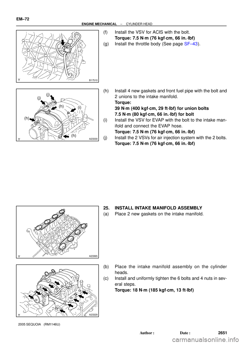
(f) Install the VSV for ACIS with the bolt.
Torque: 7.5 N´m (76 kgf´cm, 66 in.´lbf)
(g) Install the throttle body (See page SF±43).
(h) Install 4 new gaskets and front fuel pipe with the bolt and
2 unions to the intake manifold.
Torque:
39 N´m (400 kgf´cm, 29 ft´lbf) for union bolts
7.5 N´m (80 kgf´cm, 66 in.´lbf) for bolt
(i) Install the VSV for EVAP with the bolt to the intake man-
ifold and connect the EVAP hose.
Torque: 7.5 N´m (76 kgf´cm, 66 in.´lbf)
(j) Install the 2 VSVs for air injection system with the 2 bolts.
Torque: 7.5 N´m (76 kgf´cm, 66 in.´lbf)
25. INSTALL INTAKE MANIFOLD ASSEMBLY
(a) Place 2 new gaskets on the intake manifold.
(b) Place the intake manifold assembly on the cylinder
heads.
(c) Install and uniformly tighten the 6 bolts and 4 nuts in sev-
eral steps.
Torque: 18 N´m (185 kgf´cm, 13 ft´lbf)
Page 2660 of 4323
A23328
A23327
A23325
A23326
Wire Clamp
± ENGINE MECHANICALCYLINDER HEAD
EM±73
2652 Author�: Date�:
2005 SEQUOIA (RM1146U)
(d) Install the throttle body cover bracket to the intake man-
ifold.
Torque: 7.5 N´m (76 kgf´cm, 66 in.´lbf)
(e) Install the wire bracket to the intake manifold with the bolt.
Torque: 7.5 N´m (76 kgf´cm, 66 in.´lbf)
(f) Connect the engine wire to the engine hanger and wire
bracket.
(g) Install the engine wire to the LH No.1 timing belt rear
plate.
(h) Connect the wire protector to the intake manifold and cyl-
inder heads with the 2 bolts.
(i) Install the 2 ground cables with the 2 bolts to the RH and
LH cylinder heads.
(j) Connect the 2 water bypass hoses to the throttle body.
(k) Connect the 2 wire clamps to the wire clamp bracket on
the RH delivery pipe.
Page 2661 of 4323

(b)
(c)
(d)
EM±74
± ENGINE MECHANICALCYLINDER HEAD
2653 Author�: Date�:
2005 SEQUOIA (RM1146U)
26. CONNECT HOSES TO INTAKE MANIFOLD
(a) Connect the vacuum hose to the fuel pressure reg")
A23324
(a)
(b)
(c)
(d)
EM±74
± ENGINE MECHANICALCYLINDER HEAD
2653 Author�: Date�:
2005 SEQUOIA (RM1146U)
26. CONNECT HOSES TO INTAKE MANIFOLD
(a) Connect the vacuum hose to the fuel pressure regulator.
(b) Connect the PCV hose to the PCV valve on the LH the cyl-
inder head.
(c) Connect the EVAP hose (from charcoal canister) to the
VSV for EVAP.
(d) Connect the 2 vacuum hoses to the VSV for the air injec-
tion system.
(e) Connect the brake booster tube.
27. CONNECT CONNECTORS TO INTAKE MANIFOLD
(a) Connect the throttle control connector.
(b) Connect the 2 VSV connectors for the air injection sys-
tem.
(c) Connect the VSV connector for the EVAP.
(d) Connect the 8 injector connectors.
(e) Connect the ECT sensor connector.
(f) Connect the 2 air fuel ratio sensor connectors.
28. CONNECT FUEL INLET HOSE (See page SF±31) AND
FUEL RETURN HOSE
29. INSTALL TIMING BELT REAR PLATES
(a) Install the RH No.1 timing belt rear plates.
Install the RH No.1 timing belt rear plates to the cylinder
head with the 3 bolts and stud bolt.
Torque: 7.5 N´m (76 kgf´cm, 66 in.´lbf)
(b) Install the LH No.1 timing belt rear plates.
(1) Connect the wire clamp to the No.1 timing belt rear
plate.
(2) Install the LH No.1 timing belt rear plates to the cyl-
inder head with the 3 bolts and stud bolt.
Torque: 7.5 N´m (76 kgf´cm, 66 in.´lbf)
30. INSTALL THROTTLE BODY COVER
31. INSTALL IGNITION COILS (See page IG±6)
32. INSTALL OIL DIPSTICK AND GUIDE FOR A/T
33. INSTALL FRONT EXHAUST PIPE (See page EM±126)
34. INSTALL PS PUMP (See page EM±83)
35. INSTALL CAMSHAFT POSITION SENSOR
(See page IG±9)
36. INSTALL CAMSHAFT TIMING PULLEYS
(See page EM±23)
37. CONNECT TIMING BELT TO CAMSHAFT TIMING PUL-
LEYS (See page EM±23)
38. CHECK ENGINE OIL LEVEL
Page 2662 of 4323
EM11Z±07
A21014
MAF Meter Connector
PS Air HoseHood
Windshield Washer Hose
Engine Under Cover PCV Hose Vacuum Hose
Fan with Fluid Coupling Assembly
Drive Belt
Fan
Pulley
Throttle Body Cover
Radiator Assembly
No.2 Fan
Shroud Air Cleaner and
Intake Air Connector
AssemblyAir Cleaner Case
Air Filter
N´m (kgf´cm, ft´lbf) : Specified torqueMAF Meter Wire
Clip
A/T Oil Cooler Hose
12 (120, 9)29 (296, 21)
Clip
Suction Hose
29 (296, 21)
± ENGINE MECHANICALENGINE UNIT (2WD)
EM±75
2654 Author�: Date�:
2005 SEQUOIA (RM1146U)
ENGINE UNIT (2WD)
COMPONENTS