Page 2639 of 4323
A04022
A23346
A23347
Turn
EM3322
A04083
Plastigage
EM±52
± ENGINE MECHANICALCYLINDER HEAD
2631 Author�: Date�:
2005 SEQUOIA (RM1146U)
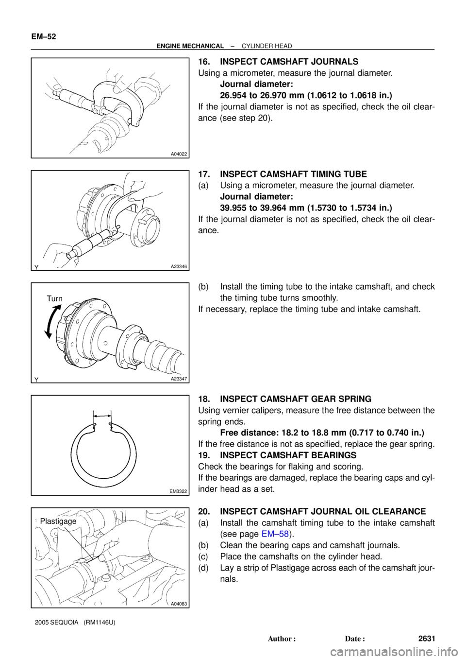
16. INSPECT CAMSHAFT JOURNALS
Using a micrometer, measure the journal diameter.
Journal diameter:
26.954 to 26.970 mm (1.0612 to 1.0618 in.)
If the journal diameter is not as specified, check the oil clear-
ance (see step 20).
17. INSPECT CAMSHAFT TIMING TUBE
(a) Using a micrometer, measure the journal diameter.
Journal diameter:
39.955 to 39.964 mm (1.5730 to 1.5734 in.)
If the journal diameter is not as specified, check the oil clear-
ance.
(b) Install the timing tube to the intake camshaft, and check
the timing tube turns smoothly.
If necessary, replace the timing tube and intake camshaft.
18. INSPECT CAMSHAFT GEAR SPRING
Using vernier calipers, measure the free distance between the
spring ends.
Free distance: 18.2 to 18.8 mm (0.717 to 0.740 in.)
If the free distance is not as specified, replace the gear spring.
19. INSPECT CAMSHAFT BEARINGS
Check the bearings for flaking and scoring.
If the bearings are damaged, replace the bearing caps and cyl-
inder head as a set.
20. INSPECT CAMSHAFT JOURNAL OIL CLEARANCE
(a) Install the camshaft timing tube to the intake camshaft
(see page EM±58).
(b) Clean the bearing caps and camshaft journals.
(c) Place the camshafts on the cylinder head.
(d) Lay a strip of Plastigage across each of the camshaft jour-
nals.
Page 2640 of 4323
A04099A A
A04084
A23348
± ENGINE MECHANICALCYLINDER HEAD
EM±53
2632 Author�: Date�:
2005 SEQUOIA (RM1146U)
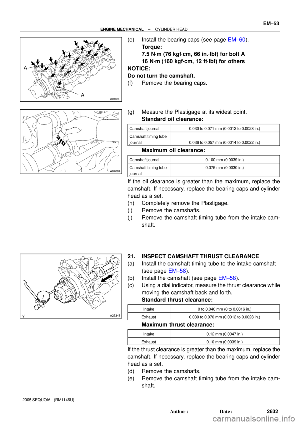
(e) Install the bearing caps (see page EM±60).
Torque:
7.5 N´m (76 kgf´cm, 66 in.´lbf) for bolt A
16 N´m (160 kgf´cm, 12 ft´lbf) for others
NOTICE:
Do not turn the camshaft.
(f) Remove the bearing caps.
(g) Measure the Plastigage at its widest point.
Standard oil clearance:
Camshaft journal0.030 to 0.071 mm (0.0012 to 0.0028 in.)
Camshaft timing tube
journal
0.036 to 0.057 mm (0.0014 to 0.0022 in.)
Maximum oil clearance:
Camshaft journal0.100 mm (0.0039 in.)
Camshaft timing tube
journal0.075 mm (0.0030 in.)
If the oil clearance is greater than the maximum, replace the
camshaft. If necessary, replace the bearing caps and cylinder
head as a set.
(h) Completely remove the Plastigage.
(i) Remove the camshafts.
(j) Remove the camshaft timing tube from the intake cam-
shaft.
21. INSPECT CAMSHAFT THRUST CLEARANCE
(a) Install the camshaft timing tube to the intake camshaft
(see page EM±58).
(b) Install the camshaft (see page EM±58).
(c) Using a dial indicator, measure the thrust clearance while
moving the camshaft back and forth.
Standard thrust clearance:
Intake0 to 0.040 mm (0 to 0.0016 in.)
Exhaust0.030 to 0.070 mm (0.0012 to 0.0028 in.)
Maximum thrust clearance:
Intake0.12 mm (0.0047 in.)
Exhaust0.10 mm (0.0039 in.)
If the thrust clearance is greater than the maximum, replace the
camshaft. If necessary, replace the bearing caps and cylinder
head as a set.
(d) Remove the camshafts.
(e) Remove the camshaft timing tube from the intake cam-
shaft.
Page 2641 of 4323
A04082
A03209
A03201
12.3 to 12.7 mm
EM±54
± ENGINE MECHANICALCYLINDER HEAD
2633 Author�: Date�:
2005 SEQUOIA (RM1146U)
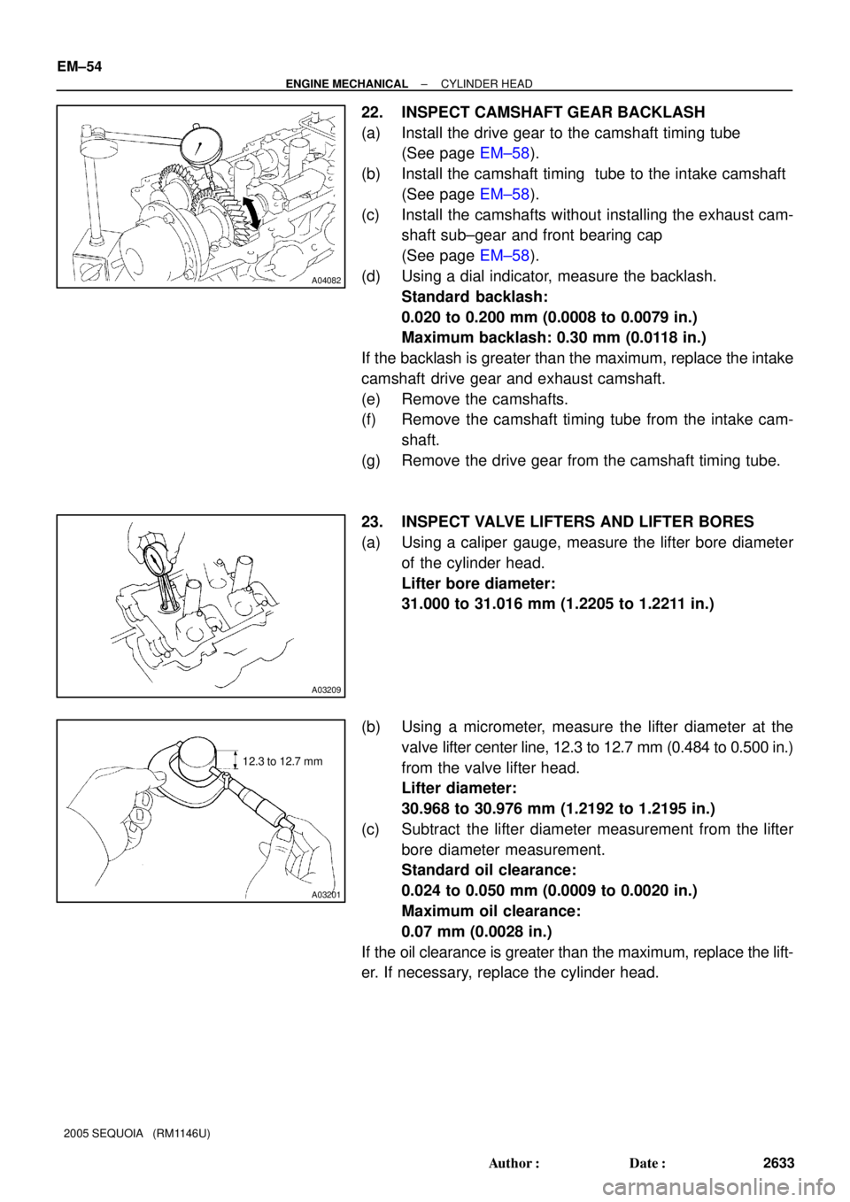
22. INSPECT CAMSHAFT GEAR BACKLASH
(a) Install the drive gear to the camshaft timing tube
(See page EM±58).
(b) Install the camshaft timing tube to the intake camshaft
(See page EM±58).
(c) Install the camshafts without installing the exhaust cam-
shaft sub±gear and front bearing cap
(See page EM±58).
(d) Using a dial indicator, measure the backlash.
Standard backlash:
0.020 to 0.200 mm (0.0008 to 0.0079 in.)
Maximum backlash: 0.30 mm (0.0118 in.)
If the backlash is greater than the maximum, replace the intake
camshaft drive gear and exhaust camshaft.
(e) Remove the camshafts.
(f) Remove the camshaft timing tube from the intake cam-
shaft.
(g) Remove the drive gear from the camshaft timing tube.
23. INSPECT VALVE LIFTERS AND LIFTER BORES
(a) Using a caliper gauge, measure the lifter bore diameter
of the cylinder head.
Lifter bore diameter:
31.000 to 31.016 mm (1.2205 to 1.2211 in.)
(b) Using a micrometer, measure the lifter diameter at the
valve lifter center line, 12.3 to 12.7 mm (0.484 to 0.500 in.)
from the valve lifter head.
Lifter diameter:
30.968 to 30.976 mm (1.2192 to 1.2195 in.)
(c) Subtract the lifter diameter measurement from the lifter
bore diameter measurement.
Standard oil clearance:
0.024 to 0.050 mm (0.0009 to 0.0020 in.)
Maximum oil clearance:
0.07 mm (0.0028 in.)
If the oil clearance is greater than the maximum, replace the lift-
er. If necessary, replace the cylinder head.
Page 2642 of 4323
A23376
± ENGINE MECHANICALCYLINDER HEAD
EM±55
2634 Author�: Date�:
2005 SEQUOIA (RM1146U)
24. INSPECT EXHAUST MANIFOLDS
Using a precision straight edge and feeler gauge, measure the
warapage of the surface that is in contact with the cylinder
head.
Maximum warpage: 0.10 mm (0.0394 in.)
If warpage is greater than maximum, replace the manifold.
Page 2643 of 4323
EM0L3±08
A03195
80 to 100°C
A05708
SST
A03197
Use STD Bushing size
10.285 to 10.306 Bushing bore diameter Both intake and exhaust(0.4049 to 0.4057)
Use O/S STD mm (in.)
(0.4069 to 0.4077)10.335 to 10.356
P21844
34.5 mm
(1.358 in.)
40.5 mm
(1.594 in.) Intake Exhaust EM±56
± ENGINE MECHANICALCYLINDER HEAD
2635 Author�: Date�:
2005 SEQUOIA (RM1146U)
REPLACEMENT
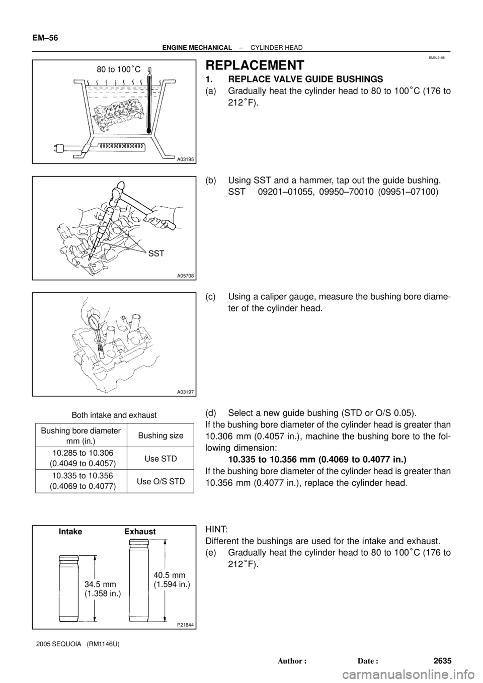
1. REPLACE VALVE GUIDE BUSHINGS
(a) Gradually heat the cylinder head to 80 to 100°C (176 to
212°F).
(b) Using SST and a hammer, tap out the guide bushing.
SST 09201±01055, 09950±70010 (09951±07100)
(c) Using a caliper gauge, measure the bushing bore diame-
ter of the cylinder head.
(d) Select a new guide bushing (STD or O/S 0.05).
If the bushing bore diameter of the cylinder head is greater than
10.306 mm (0.4057 in.), machine the bushing bore to the fol-
lowing dimension:
10.335 to 10.356 mm (0.4069 to 0.4077 in.)
If the bushing bore diameter of the cylinder head is greater than
10.356 mm (0.4077 in.), replace the cylinder head.
HINT:
Different the bushings are used for the intake and exhaust.
(e) Gradually heat the cylinder head to 80 to 100°C (176 to
212°F).
Page 2644 of 4323
A05709
SST
A03199A03200
Sharp 5.5 mm Reamer
A04107
Pry
ClawBend
A04108
SST
SST Return
ClawDownward
± ENGINE MECHANICALCYLINDER HEAD
EM±57
2636 Author�: Date�:
2005 SEQUOIA (RM1146U)
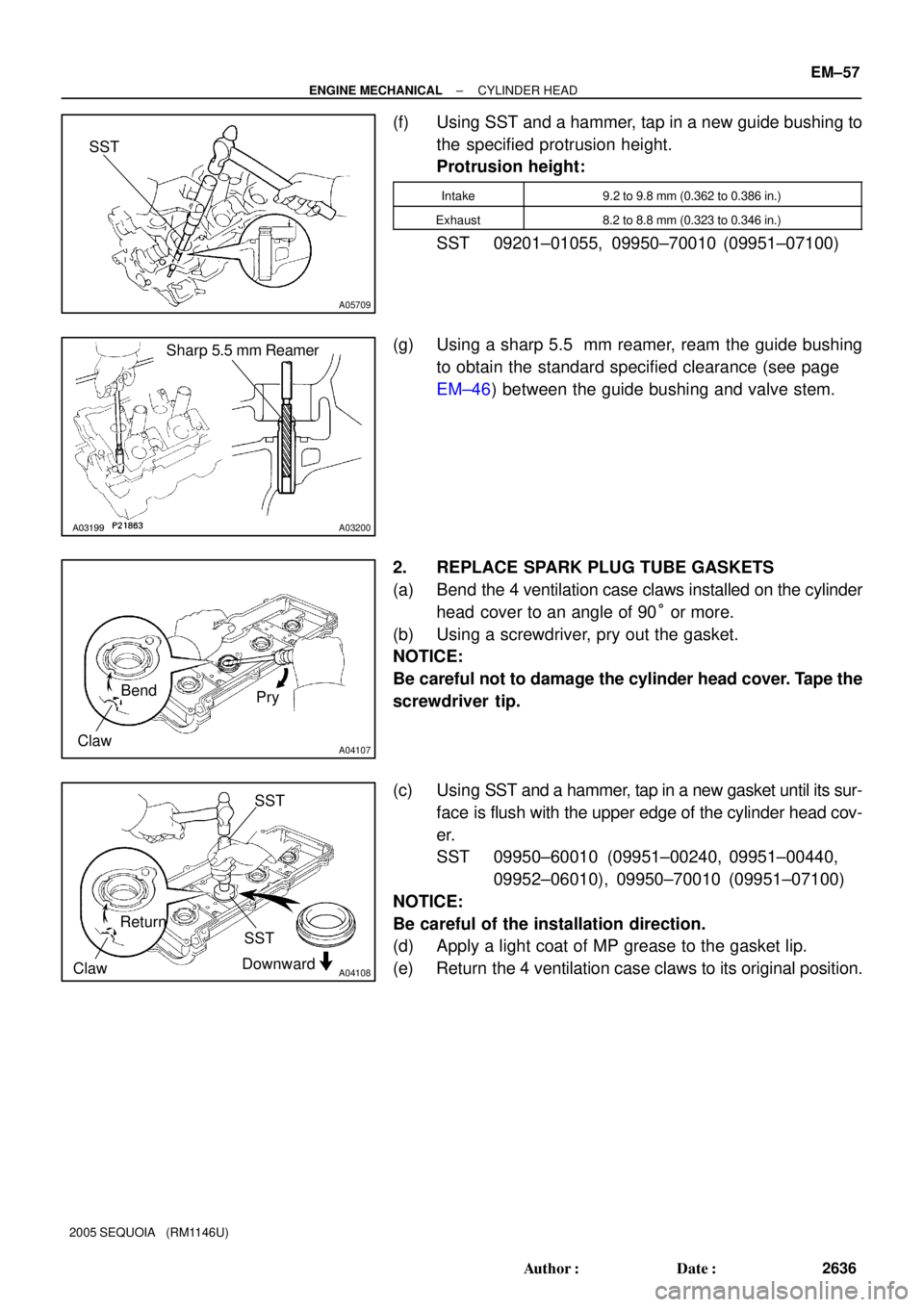
(f) Using SST and a hammer, tap in a new guide bushing to
the specified protrusion height.
Protrusion height:
Intake9.2 to 9.8 mm (0.362 to 0.386 in.)
Exhaust8.2 to 8.8 mm (0.323 to 0.346 in.)
SST 09201±01055, 09950±70010 (09951±07100)
(g) Using a sharp 5.5 mm reamer, ream the guide bushing
to obtain the standard specified clearance (see page
EM±46) between the guide bushing and valve stem.
2. REPLACE SPARK PLUG TUBE GASKETS
(a) Bend the 4 ventilation case claws installed on the cylinder
head cover to an angle of 90° or more.
(b) Using a screwdriver, pry out the gasket.
NOTICE:
Be careful not to damage the cylinder head cover. Tape the
screwdriver tip.
(c) Using SST and a hammer, tap in a new gasket until its sur-
face is flush with the upper edge of the cylinder head cov-
er.
SST 09950±60010 (09951±00240, 09951±00440,
09952±06010), 09950±70010 (09951±07100)
NOTICE:
Be careful of the installation direction.
(d) Apply a light coat of MP grease to the gasket lip.
(e) Return the 4 ventilation case claws to its original position.
Page 2645 of 4323
EM0L4±09
P08885
Adhesive
15 mm (0.59 in.)
A03212
Protrusion
A05710
SST
A05711
(1)(2)(3)(4)
EM±58
± ENGINE MECHANICALCYLINDER HEAD
2637 Author�: Date�:
2005 SEQUOIA (RM1146U)
REASSEMBLY
HINT:
�Thoroughly clean all parts to be assembled.
�Before installing the parts, apply fresh engine oil to all slid-
ing and rotating surfaces.
�Replace all gaskets and oil seals with new ones.
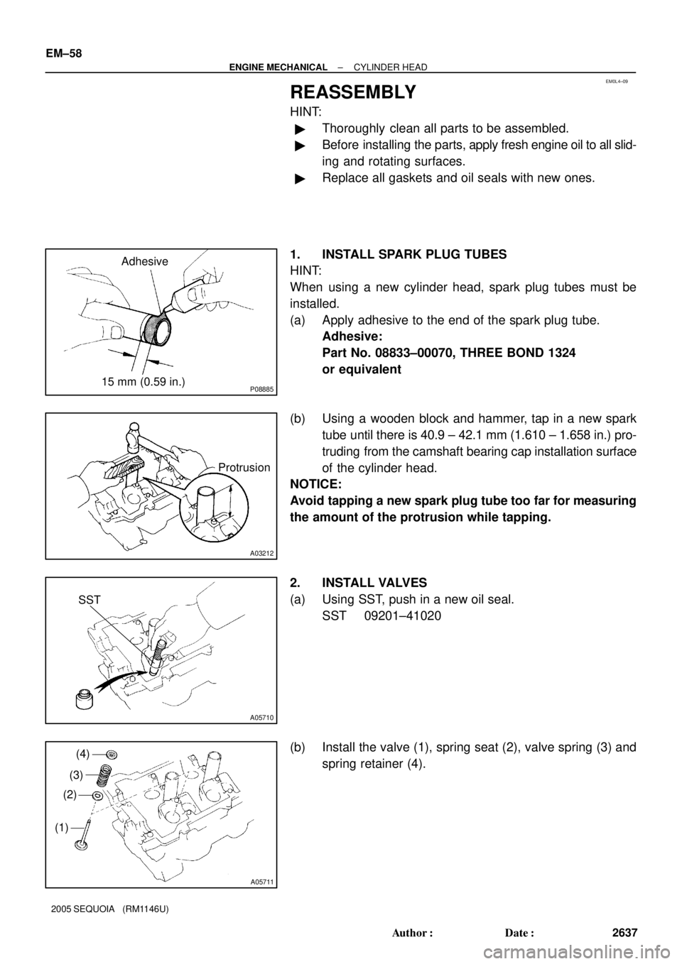
1. INSTALL SPARK PLUG TUBES
HINT:
When using a new cylinder head, spark plug tubes must be
installed.
(a) Apply adhesive to the end of the spark plug tube.
Adhesive:
Part No. 08833±00070, THREE BOND 1324
or equivalent
(b) Using a wooden block and hammer, tap in a new spark
tube until there is 40.9 ± 42.1 mm (1.610 ± 1.658 in.) pro-
truding from the camshaft bearing cap installation surface
of the cylinder head.
NOTICE:
Avoid tapping a new spark plug tube too far for measuring
the amount of the protrusion while tapping.
2. INSTALL VALVES
(a) Using SST, push in a new oil seal.
SST 09201±41020
(b) Install the valve (1), spring seat (2), valve spring (3) and
spring retainer (4).
Page 2646 of 4323
A05712SST
A07306
Vinyl Tape
± ENGINE MECHANICALCYLINDER HEAD
EM±59
2638 Author�: Date�:
2005 SEQUOIA (RM1146U)
(c) Using SST, compress the valve spring and place the 2
keepers around the valve stem.
SST 09202±70020 (09202±00010)
(d) Using a plastic±faced hammer and the valve stem (not in
use) tip wound with vinyl tape, lightly tap the valve stem
tip to assure proper fit.
NOTICE:
Be careful not to damage the valve stem tip.
3. INSTALL SHIMS AND VALVE LIFTERS
(a) Install the shim and valve lifter.
(b) Check that the valve lifter rotates smoothly by hand.