Page 2623 of 4323

REMOVAL
1. DRAIN ENGINE COOLANT
2. REMOVE THROTTLE BODY COVER
3. DISCONNECT TIMING BELT FROM CAM")
EM1X0±01
A02844
EM±36
± ENGINE MECHANICALCYLINDER HEAD
2615 Author�: Date�:
2005 SEQUOIA (RM1146U)
REMOVAL
1. DRAIN ENGINE COOLANT
2. REMOVE THROTTLE BODY COVER
3. DISCONNECT TIMING BELT FROM CAMSHAFT TIM-
ING PULLEYS (See page EM±16)
NOTICE:
�Be careful not to drop anything inside the timing belt
cover.
�Do not allow the belt to come into correct with oil, wa-
ter or dust.
4. REMOVE CAMSHAFT TIMING PULLEYS
(See page EM±16)
5. REMOVE CAMSHAFT POSITION SENSOR
(See page IG±8)
6. DISCONNECT PS PUMP FROM ENGINE
(See page EM±79)
7. REMOVE FRONT EXHAUST PIPE (See page EM±126)
8. REMOVE OIL DIPSTICK AND GUIDE FOR A/T
9. REMOVE IGNITION COILS (See page IG±5)
10. REMOVE TIMING BELT REAR PLATES
(a) Remove the 3 bolts, stud bolt and RH No.1 timing belt rear
plates.
(b) Disconnect the wire clamp from the LH timing belt rear
plate.
(c) Remove the 3 bolts, stud bolt and LH No.1 timing belt rear
plates.
11. DISCONNECT FUEL INLET HOSE (See page SF±27)
AND FUEL RETURN HOSE
12. DISCONNECT CONNECTORS FROM INTAKE MAN-
IFOLD
(a) Disconnect the throttle control connector.
(b) Disconnect the VSV connector for EVAP.
(c) Disconnect the 8 injector connectors.
(d) Disconnect the ECT sensor connector.
(e) Disconnect the 2 VSV connectors for the air injection sys-
tem.
(f) Disconnect the 8 ignition coil connectors.
(g) Disconnect the 2 air fuel ratio sensor connectors.
Page 2624 of 4323
A23324
(a)
(b)
(c)
(d)
A23325Water Bypass Hose
A23326
A23327
± ENGINE MECHANICALCYLINDER HEAD
EM±37
2616 Author�: Date�:
2005 SEQUOIA (RM1146U)
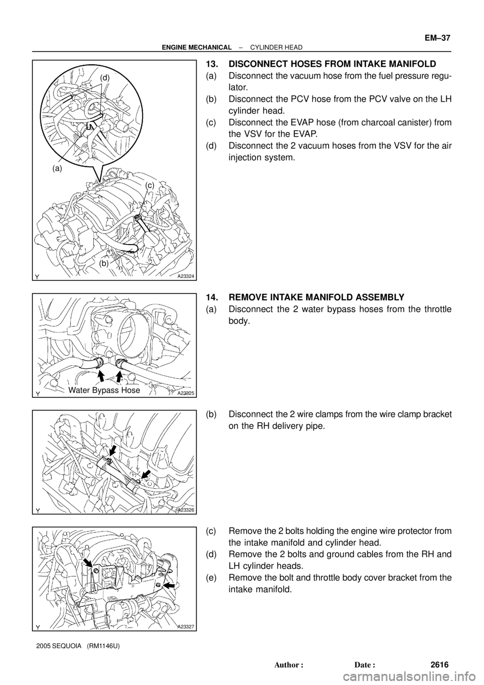
13. DISCONNECT HOSES FROM INTAKE MANIFOLD
(a) Disconnect the vacuum hose from the fuel pressure regu-
lator.
(b) Disconnect the PCV hose from the PCV valve on the LH
cylinder head.
(c) Disconnect the EVAP hose (from charcoal canister) from
the VSV for the EVAP.
(d) Disconnect the 2 vacuum hoses from the VSV for the air
injection system.
14. REMOVE INTAKE MANIFOLD ASSEMBLY
(a) Disconnect the 2 water bypass hoses from the throttle
body.
(b) Disconnect the 2 wire clamps from the wire clamp bracket
on the RH delivery pipe.
(c) Remove the 2 bolts holding the engine wire protector from
the intake manifold and cylinder head.
(d) Remove the 2 bolts and ground cables from the RH and
LH cylinder heads.
(e) Remove the bolt and throttle body cover bracket from the
intake manifold.
Page 2625 of 4323
(a)
(b)(c)
(c) (c)
B17510
A23331
EM±38
± ENGINE MECHANICALCYLINDER HEAD
2617 Author�: Date�:
2005 SEQUOIA (RM1146U)
(f) Disconnect the engine wire from the engine hanger a")
A23328
A23329
A23330
(a)(a)
(b)(c)
(c) (c)
B17510
A23331
EM±38
± ENGINE MECHANICALCYLINDER HEAD
2617 Author�: Date�:
2005 SEQUOIA (RM1146U)
(f) Disconnect the engine wire from the engine hanger and
wire bracket.
(g) Remove the wire bracket from the intake manifold.
(h) Remove the 6 bolts, 4 nuts, intake manifold assembly and
2 gaskets.
15. DISASSEMBLE INTAKE MANIFOLD
(a) Remove the 2 bolts and VSVs for the air injection system.
(b) Disconnect the EVAP hose from the upper intake man-
ifold, and remove the VSV for EVAP.
(c) Remove the bolt, 2 unions, 4 gaskets and front fuel pipe
from the intake manifold.
(d) Remove the throttle body (see page SF±42).
(e) Remove the bolt and VSV for ACIS from the intake man-
ifold.
(f) Disconnect the fuel return hose from the fuel pressure
regulator.
(g) Remove the 3 bolts and fuel return pipe from the intake
manifold.
(h) Remove the 2 bolts, fuel pressure regulator and O±ring.
(i) Remove the fuel pressure pulsation damper and 2 gas-
kets.
(j) Remove the 2 delivery pipes and 8 injectors (see page
SF±27).
Page 2626 of 4323

16. REMOVE WATER INLET AND INLET HOUSING AS")
A23332
Front Water Bypass Joint
A23333
Rear Water Bypass Joint
A05564
± ENGINE MECHANICALCYLINDER HEAD
EM±39
2618 Author�: Date�:
2005 SEQUOIA (RM1146U)
16. REMOVE WATER INLET AND INLET HOUSING AS-
SEMBLY (See page CO±6)
17. REMOVE AIR PUMP ASSEMBLY (See page EC±22)
18. REMOVE NO.2 AIR SWITCHING VALVES
(See page EC±22)
19. REMOVE FRONT WATER BYPASS JOINT
Remove the 4 nuts, water bypass joint and 2 gaskets.
20. REMOVE REAR WATER BYPASS JOINT
Remove the 4 nuts, water bypass joint and 2 gaskets.
21. REMOVE ENGINE HANGERS
22. REMOVE CYLINDER HEAD COVERS
Remove the 18 bolts, seal washers, RH and LH cylinder head
covers and 2 gaskets.
23. IF NECESSARY, REMOVE SEMI±CIRCULAR PLUGS
AND CAMSHAFT HOUSING PLUGS
24. REMOVE CAMSHAFTS
NOTICE:
Since the thrust clearance of the camshaft is small, the
camshaft must be kept level while it is being removed. If the
camshaft is not kept level, the portion of the cylinder head
receiving the shaft thrust may crack or be damaged, caus-
ing the camshaft to seize or break. To avoid this, the follow-
ing steps should be carried out.
Page 2627 of 4323

SSTOil Control Valve
Installation Hole
A23335Service Bolt
A23336
EM±40
± ENGINE MECHANICALCYLINDER HEAD
2619 A")
A04456
No.2 Idler
Pulley Bolt
Timing
Mark
Crankshaft
Pulley Bolt
A23334
Movement
(25°)
SSTOil Control Valve
Installation Hole
A23335Service Bolt
A23336
EM±40
± ENGINE MECHANICALCYLINDER HEAD
2619 Author�: Date�:
2005 SEQUOIA (RM1146U)
(a) Check the crankshaft pulley position.
Check that the timing mark of the crankshaft pulley is
aligned with the centers of the crankshaft pulley bolt and
idler pulley bolt.
NOTICE:
Having the crankshaft pulley at the wrong angle can cause
the piston head and valve head to come into contact with
each other when you remove the camshaft, causing dam-
age. So always set the crankshaft pulley at the correct
angle.
(b) Release the oil from the front bearing caps.
Using SST, rotate the camshaft timing tube from left to
right 2 to 3 times within its VVT±i range (25°) and use a
waste cloth to collect the oil from the camshaft timing oil
control valve installation hole.
SST 09960±10010 (09962±01000, 09963±00400)
NOTICE:
Approximately 20 cc (1.2 cu in.) of oil will be ejected. Take
care not to spill it.
(c) Remove the LH camshafts.
(1) Bring the service bolt hole of the sub±gear upward
by turning the hexagon head portion of the exhaust
camshaft with a wrench.
(2) Secure the sub±gear to the main gear with a service
bolt.
Recommended service bolt:
Thread diameter6 mm
Thread pitch1.0 mm
Bolt length16 to 20 mm (0.63 to 0.79 in.)
HINT:
When removing the camshaft, make sure that the torsional
spring force of the sub±gear has been eliminated by the above
operation.
(3) Align the timing mark (2±dot mark) of the camshaft
drive gear by turning the hexagon head portion of
the exhaust camshaft with a wrench.
Page 2628 of 4323

A23337
12
345
6
7
811
12 13
14
15
1617
18 2122
910 1920
A23338
Service Bolt
A23339
Approx.
10°
A23340
1 2
21
22
19 20
7
8 11
12
13
14
15
16
3
4 17
18
5
6 9
10
± ENGINE MECHANICALCYLINDER HEAD
EM±41
2620 Author�: Date�:
2005 SEQUOIA (RM1146U)
(4) Uniformly loosen the 22 bearing cap bolts in several
steps, in the sequence shown.
(5) Remove the 22 bearing cap bolts, 4 seal washers,
oil feed pipe, 9 bearing caps, camshaft housing
plug, oil control valve filter and 2 camshafts.
(d) Remove the RH camshafts.
(1) Bring the service bolt hole of the sub±gear upward
by turning the hexagon head portion of the exhaust
camshaft with a wrench.
(2) Secure the sub±gear to the main gear with a service
bolt.
Recommended service bolt:
Thread diameter6 mm
Thread pitch1.0 mm
Bolt length16 to 20 mm (0.63 to 0.79 in.)
HINT:
When removing the camshafts, make sure that the torsional
spring force of the sub±gear has been eliminated by the above
operation.
(3) Set the timing mark (1±dot mark) of the camshaft
main gear at approx. 10° angle by turning the hexa-
gon head portion of the exhaust camshaft with a
wrench.
(4) Uniformly loosen the 22 bearing cap bolts in several
steps, in the sequence shown.
(5) Remove the 22 bearing cap bolts, 4 seal washers,
oil feed pipe, 9 bearing caps, camshaft housing
plug, strainer and 2 camshafts.
HINT:
Arrange the bearing caps for RH and LH sides.
Page 2629 of 4323

25. DISASSEMBLE EXHAU")
A02859
A02850
SST
Service Bolt
Turn
A02861
A23341
Do Not Remove
A23342
10 mm
Hexagon
Wrench
EM±42
± ENGINE MECHANICALCYLINDER HEAD
2621 Author�: Date�:
2005 SEQUOIA (RM1146U)
25. DISASSEMBLE EXHAUST CAMSHAFTS
(a) Mount the hexagon head portion of the camshaft in a vise.
NOTICE:
Be careful not to damage the camshaft.
(b) Using SST, turn the sub±gear clockwise, and remove the
service bolt.
SST 09960±10010 (09962±01000, 09963±00500)
(c) Using snap ring pliers, remove the snap ring.
(d) Remove the wave washer.
(e) Remove the camshaft sub±gear.
(f) Remove the camshaft gear spring.
NOTICE:
Be careful not to damage the camshaft.
26. REMOVE CAMSHAFT TIMING TUBE FROM INTAKE
CAMSHAFT
(a) Mount the hexagon head portion of the intake camshaft
in a vise.
NOTICE:
�Be careful not to damage the camshaft.
�The 4 bolts shown in the illustration determine back-
lash of the gear in the timing tube, so do not remove
them. If any of the 4 bolts are removed, install a new
timing tube assembly.
(b) Remove the screw plug and seal washer.
(c) Using a 10 mm hexagon wrench, and remove the bolt.
(d) Pull out the timing tube and drive gear assembly from the
camshaft.
Page 2630 of 4323

A233435 mm Hexagon Wrench SST
B02642B02644A04229
RH Bank
LH Bank1
23 4
5 6
7
89
10
3
1 5
7 10
9 8
6 2
4
B02643
B02645A04230
Portion A
Portion A RH Bank
LH Bank
± ENGINE MECHANICALCYLINDER HEAD
EM±43
2622 Author�: Date�:
2005 SEQUOIA (RM1146U)
(e) Using SST and a 5 mm hexagon wrench, remove the 4
bolts, drive gear and oil seal.
SST 09960±10010 (09962±01000, 09963±00500)
NOTICE:
Be careful not to damage the timing tube.
27. REMOVE SPARK PLUGS
28. REMOVE CYLINDER HEAD AND EXHAUST MAN-
IFOLD ASSEMBLIES
(a) Uniformly loosen the 10 cylinder head bolts on one side
of each cylinder head in several steps, in the sequence
shown, then perform the same procedure to the other
side as shown. Remove the 20 cylinder head bolts and
plate washers.
NOTICE:
�Cylinder head warpage or cracking could result from
removing bolts in incorrect order.
�Do not drop the plate washer for cylinder head bolt
into portion A of the cylinder head. If dropped into
portion A, the plate washer will pass through the cyl-
inder head and cylinder block into the oil pan.