Page 2591 of 4323

VALVE CLEARANCE
INSPECTION
HINT:
Inspect and adjust the valve clearance when the engine")
EM0KS±09
A23300
A23301
EM±4
± ENGINE MECHANICALVALVE CLEARANCE
2583 Author�: Date�:
2005 SEQUOIA (RM1146U)
VALVE CLEARANCE
INSPECTION
HINT:
Inspect and adjust the valve clearance when the engine is cold.
1. REMOVE BATTERY CLAMP COVER
2. REMOVE THROTTLE BODY COVER
3. REMOVE AIR CLEANER AND INTAKE AIR CONNEC-
TOR ASSEMBLY
4. REMOVE NO.3 TIMING BELT COVERS
(See page EM±16)
5. REMOVE IGNITION COILS (See page IG±5)
6. REMOVE RH CYLINDER HEAD COVER
Remove the 9 bolts, seal washers and cylinder head cover.
7. REMOVE LH CYLINDER HEAD COVER
(a) Remove the oil dipstick for the transmission.
(b) Disconnect the PCV hose.
(c) Disconnect the engine wire clamp from the wire bracket
on the cylinder head cover.
(d) Remove the 9 bolts, 9 seal washers and cylinder head
cover.
8. SET NO.1 CYLINDER TO TDC/COMPRESSION
(a) Turn the crankshaft pulley, and align its groove with timing
mark º0º of the No.1 timing belt cover.
(b) Check that the timing marks of the camshaft timing pul-
leys and timing belt rear plates are aligned.
If not, turn the crankshaft 1 revolution (360°) and align the mark
as above.
Page 2592 of 4323
A05717
RH Cylinder Head
LH Cylinder HeadFront
A04457
RH Cylinder Head
LH Cylinder Head
Front
± ENGINE MECHANICALVALVE CLEARANCE
EM±5
2584 Author�: Date�:
2005 SEQUOIA (RM1146U)
9. INSPECT VALVE CLEARANCE
(a) Check only the valves indicated.
�Using a feeler gauge, measure the clearance be-
tween the valve lifter and camshaft.
�Record the out±of±specification valve clearance
measurements. They will be used later to determine
the required replacement adjusting shim.
Valve clearance (Cold):
Intake0.15 ± 0.25 mm (0.006 ± 0.010 in.)
Exhaust0.25 ± 0.35 mm (0.010 ± 0.014 in.)
(b) Turn the crankshaft 1 revolution (360°) and align the mark
as above. (See procedure in step 8)
(c) Check only the valves indicated as shown. Measure the
valve clearance. (See procedure in step (a))
Page 2593 of 4323

10. ADJUST VALVE CLEARANCE
(a) Remove the timing belt. (See page EM±16)
(b) Remove the camshafts. (See p")
A02213
EM±6
± ENGINE MECHANICALVALVE CLEARANCE
2585 Author�: Date�:
2005 SEQUOIA (RM1146U)
10. ADJUST VALVE CLEARANCE
(a) Remove the timing belt. (See page EM±16)
(b) Remove the camshafts. (See page EM±36)
(c) Remove the valve lifter and adjusting shim.
(d) Determine the replacement adjusting shim size according
to these Formula or Charts:
(1) Using a micrometer, measure the thickness of the
removed shim.
(2) Calculate the thickness of a new shim so that the
valve clearance comes within the specified value.
T ........... Thickness of removed shim
A ........... Measured valve clearance
N ........... Thickness of new shim
Intake: N = T + (A ± 0.20 mm (0.008 in.))
Exhaust: N = T + (A ± 0.30 mm (0.012 in.))
(3) Select a new shim with thickness as close as pos-
sible to the calculated value.
HINT:
Shims are available in 41 increments of 0.020 mm (0.0008 in.),
from 2.00 mm (0.0787 in.) to 2.80 mm (0.1102 in.).
(e) Place a new adjusting shim on the valve.
(f) Place the valve lifter.
(g) Reinstall the camshafts. (See page EM±60)
(h) Reinstall the timing belt. (See page EM±23)
(i) Recheck the valve clearance.
11. REINSTALL CYLINDER HEAD COVERS
12. REINSTALL IGNITION COILS
13. REINSTALL NO.3 TIMING BELT COVERS
(See page EM±23)
14. REINSTALL AIR CLEANER AND INTAKE AIR
CONNECTOR ASSEMBLY
15. REINSTALL THROTTLE BODY COVER
16. REINSTALL BATTERY CLAMP COVER
Page 2594 of 4323
A03111
Adjusting Shim Selection Chart (Intake)
Shim No. Installed shim thickness
mm (in.)
mm (in.) Measured clearance
Thickness
New shim thicknessShim No. Thickness Shim No. Thickness
mm (in.)
Intake valve clearance (Cold):
0.15 ± 0.25 mm (0.006 ± 0.010 in.)EXAMPLE:
The 2.300 mm (0.0906 in.) shim is installed,
and the measured clearance is 0.440 mm
(0.0173 in.). Replace the 2.300 mm (0.0906
in.) shim with a No. 54 shim.
± ENGINE MECHANICALVALVE CLEARANCE
EM±7
2586 Author�: Date�:
2005 SEQUOIA (RM1146U)
Page 2595 of 4323
A03112
Adjusting Shim Selection Chart (Exhaust)
Installed shim thickness
mm (in.)
mm (in.) Measured clearance
Shim No. Thickness
New shim thicknessShim No. Thickness Shim No. Thickness
mm (in.)
Exhaust valve clearance (Cold):
0.25 ± 0.35 mm (0.010 ± 0.014 in.)EXAMPLE:
The 2.300 mm (0.0906 in.) shim is installed,
and the measured clearance is 0.440 mm
(0.0173 in.). Replace the 2.300 mm (0.0906
in.) shim with a No. 44 shim.
EM±8
± ENGINE MECHANICALVALVE CLEARANCE
2587 Author�: Date�:
2005 SEQUOIA (RM1146U)
Page 2596 of 4323
EM0KT±11
D13872
Hand±Held Tester
DLC3
CAN VIM
A08769
A23394
TC
SST
DLC3
CG
± ENGINE MECHANICALIGNITION TIMING
EM±9
2588 Author�: Date�:
2005 SEQUOIA (RM1146U)
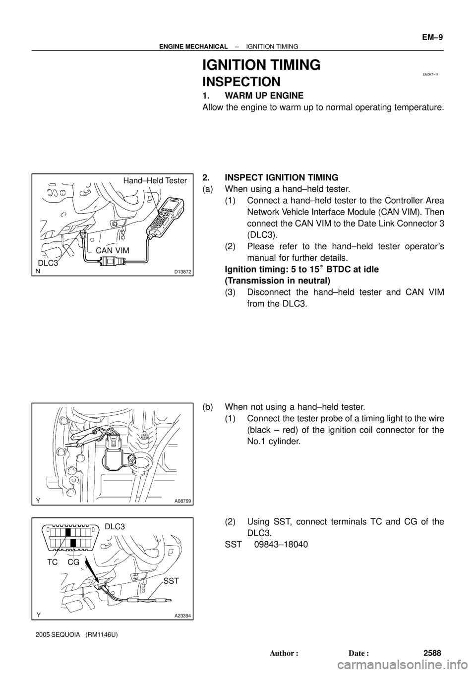
IGNITION TIMING
INSPECTION
1. WARM UP ENGINE
Allow the engine to warm up to normal operating temperature.
2. INSPECT IGNITION TIMING
(a) When using a hand±held tester.
(1) Connect a hand±held tester to the Controller Area
Network Vehicle Interface Module (CAN VIM). Then
connect the CAN VIM to the Date Link Connector 3
(DLC3).
(2) Please refer to the hand±held tester operator's
manual for further details.
Ignition timing: 5 to 15° BTDC at idle
(Transmission in neutral)
(3) Disconnect the hand±held tester and CAN VIM
from the DLC3.
(b) When not using a hand±held tester.
(1) Connect the tester probe of a timing light to the wire
(black ± red) of the ignition coil connector for the
No.1 cylinder.
(2) Using SST, connect terminals TC and CG of the
DLC3.
SST 09843±18040
Page 2597 of 4323
A04459
EM±10
± ENGINE MECHANICALIGNITION TIMING
2589 Author�: Date�:
2005 SEQUOIA (RM1146U)
(3) Using a timing light, check the ignition timing.
Ignition timing: 5 to 15° BTDC at idle
(Transmission in neutral)
(4) Remove the SST from the DLC3.
SST 09843±18040
(5) Disconnect the timing light from the engine.
Page 2598 of 4323

IDLE SPEED
INSPECTION
1. INITIAL CONDITIONS
(a)")
EM1X3±01
D13872
Hand±Held Tester
DLC3
CAN VIM
A23395
DLC3
TA C
SST
± ENGINE MECHANICALIDLE SPEED
EM±11
2590 Author�: Date�:
2005 SEQUOIA (RM1146U)
IDLE SPEED
INSPECTION
1. INITIAL CONDITIONS
(a) Engine at normal operating temperature
(b) Air cleaner installed
(c) All pipes and hoses of air induction system connected
(d) All accessories switched OFF
(e) All vacuum lines properly connected
(f) SFI system wiring connectors fully plugged
(g) iCorrect gnition timing
(h) Transmission in neutral
(i) Air conditioning switched OFF
2. INSPECT ENGINE IDLE SPEED
(a) When using a hand±held tester.
(1) Connect a hand±held tester to the Controller Area
Network Vehicle Interface Module (CAN VIM). Then
connect the CAN VIM to the Date Link Connector 3
(DLC3).
(2) Please refer to the hand±held tester operator's
manual for further details.
(3) Race the engine speed at 2,500 rpm for approx. 90
seconds.
(4) Check the idle speed.
Idle speed: 700 ± 50 rpm
(Transmission in neutral)
If the idle speed is not as specified, check the air intake system.
(5) Disconnect the hand±held tester and CAN VIM
from the DLC3.
(b) When not using a hand±held tester.
(1) Using SST, connect the tachometer probe to termi-
nal TAC of the DLC3.
SST 09843±18030
(2) Race the engine at 2,500 rpm for approx. 90 se-
conds.
(3) Check the idle speed.
Idle speed: 700 ± 50 rpm
(Transmission in neutral )
If the idle speed is not as specified, check the air intake system.


Shim No. Installed shim thickness
mm (in.)
mm (in.) Measured clearance
Thickness
New shim thicknessShim No. Thickness Shim No. Thickness
mm (in.)
Intake")

Installed shim thickness
mm (in.)
mm (in.) Measured clearance
Shim No. Thickness
New shim thicknessShim No. Thickness Shim No. Thickness
mm (in.)
Exhau")