Page 2671 of 4323

2663 Author�: Date�:
2005 SEQUOIA (RM1146U)
3. INSTALL TORQUE CONVERTER CLUTCH BOLTS
(a) Apply adhesive to")
P18747
Adhesive
A08900
A15637
A08931
Lower
Up EM±84
± ENGINE MECHANICALENGINE UNIT (2WD)
2663 Author�: Date�:
2005 SEQUOIA (RM1146U)
3. INSTALL TORQUE CONVERTER CLUTCH BOLTS
(a) Apply adhesive to 2 or 3 threads of the bolt end.
Adhesive:
Part No. 08833±00070, THREE BOND 1324 or equiva-
lent
(b) Hold the crankshaft pulley bolt with a wrench, and install
the 6 bolts evenly.
Torque: 48 N´m (490 kgf´cm, 35 ft´lbf)
HINT:
First install the black colored bolt, install the other bolts.
(c) Install the flywheel housing under cover with the bolt.
Torque: 18 N´m (185 kgf´cm, 13 ft´lbf)
4. INSTALL OIL COOLER PIPE FOR TRANSMISSION
5. INSTALL OIL DIPSTICK GUIDE AND DIPSTICK FOR
TRANSMISSION
(a) Install a new O±ring to the dipstick guide.
(b) Apply soapy water to the O±ring.
(c) Connect the dipstick guide end to the dipstick tube of the
oil pan.
(d) Install the dipstick guide with the bolt.
(e) Install the dipstick.
(f) Connect the 2 breather hoses to the dipstick guide.
6. CONNECT ENGINE WIRE TO TRANSMISSION
(a) Connect the 5 connectors.
(b) Connect the 2 wire clamps.
7. INSTALL ENGINE AND TRANSMISSION ASSEMBLY
IN VEHICLE
(a) Attach the engine chain hoist to the engine hangers.
(b) Slowly lower the engine and transmission assembly into
the engine compartment.
(c) Attach the engine mounting brackets to the frame brack-
ets.
Page 2672 of 4323
A09149
A08906
A08804
ABBB
A09147
A08907
± ENGINE MECHANICALENGINE UNIT (2WD)
EM±85
2664 Author�: Date�:
2005 SEQUOIA (RM1146U)
(d) Keep the engine level with a jack.
8. INSTALL ENGINE REAR MOUNTING BRACKET
(a) Install the engine rear mounting bracket to the transmis-
sion with the 4 bolts.
Torque: 65 N´m (663 kgf´cm, 48 ft´lbf)
(b) Install the frame crossmember with the 8 bolts and 4 nuts.
Torque:
A: 18 N´m (183 kgf´cm, 13 ft´lbf) for bolts
B: 72 N´m (730 kgf´cm, 53 ft´lbf) for nuts
9. INSTALL ENGINE MOUNTING BRACKETS
(a) Install the engine mounting brackets to the frame brack-
ets with the 2 nuts and 4 bolts.
Torque: 38 N´m (388 kgf´cm, 28 ft´lbf)
(b) Remove the engine chain hoist.
10. INSTALL PS PUMP
Install the PS pump with the 3 bolts.
Torque: 17 N´m (175 kgf´cm, 13 ft´lbf)
Page 2673 of 4323
 EM±86
± ENGINE MECHANICALENGINE UNIT (2WD)
2665 Author�: Date�:
2005 SEQUOIA (RM1146U)
11. INSTALL A/C COMPRESSOR
(a) Install the A/C compressor with the 3 bolts.
Torque: 49 N´m")
A08905
A09151
(a) EM±86
± ENGINE MECHANICALENGINE UNIT (2WD)
2665 Author�: Date�:
2005 SEQUOIA (RM1146U)
11. INSTALL A/C COMPRESSOR
(a) Install the A/C compressor with the 3 bolts.
Torque: 49 N´m (500 kgf´cm, 36 ft´lbf)
(b) Connect the A/C compressor connector.
12. INSTALL TRANSMISSION CONTROL CABLE
(a) Install the control cable to the control shift lever.
Torque: 13 N´m (130 kgf´cm, 9 ft´lbf)
(b) Install the control cable bracket to the transmission with
the 2 bolts.
13. CONNECT POWER STEERING GEAR PIPES
Connect the pressure feed tube, turn tube and turn pressure
tubes to the PS gear assembly. (See page SR±40, SR±41)
14. INSTALL FRONT STABILIZER BAR
(See page SA±93)
15. INSTALL PROPELLER SHAFT (See page PR±5)
16. INSTALL FRONT EXHAUST PIPES
(See page EM±126)
17. CONNECT HOSES, WIRES, CONNECTORS, CLAMPS,
GROMMET AND CABLES
(a) Connect the 2 PS air hoses to hose clamp on the No.3 RH
timing belt cover.
(b) Connect the generator wire.
(c) Connect the generator connector.
(d) Connect the hose clamp for the PS air hose.
(e) Connect the PS air hose to the upper intake manifold.
(f) Connect the 2 heater hoses.
(g) Connect the ground strap connector.
(h) Connect the fuel inlet hose and clamps.
(i) Connect the fuel return hose and clamp.
(j) Connect the air inlet hose to the charcoal canister.
(k) Connect the EVAP hose to the charcoal canister.
(l) Connect the brake booster tube.
18. CONNECT ENGINE WIRE TO CABIN
(a) Push into the engine wire through the cowl panel.
Page 2674 of 4323

EM±87
2666 Author�: Date�:
2005 SEQUOIA (RM1146U)
(b) Install the engine wire bracket with the 2 nuts and bolt and
connect the engine wire to t")
A09152
Connect
± ENGINE MECHANICALENGINE UNIT (2WD)
EM±87
2666 Author�: Date�:
2005 SEQUOIA (RM1146U)
(b) Install the engine wire bracket with the 2 nuts and bolt and
connect the engine wire to the bracket.
(c) Connect the 2 wire harness connectors (cassette con-
nector).
(d) Connect the 3 connectors to the ECM.
(e) Install the ECM with the 3 screws.
(f) Install the lower No.2 panel.
(g) Install the glove compartment door.
19. INSTALL FAN PULLEY, FAN, FLUID COUPLING AND
DRIVE BELT
(a) Temporarily install the fan pulley, the fan and fluid cou-
pling assembly with the 4 nuts.
(b) Install the drive belt. (See page CH±16)
(c) Tighten the 4 nuts holding the fluid coupling to the fan
bracket.
20. INSTALL AIR CLEANER AND INTAKE AIR CONNEC-
TOR ASSEMBLY
(a) Install the air cleaner with the 3 bolt.
Torque: 5.0 N´m (51 kgf´cm, 44 in.´lbf)
(b) Connect the intake air connector to the throttle body.
(c) Connect the MAF meter connector.
(d) Install the suction hose to the intake air connector.
(e) Connect the PS air hose, air inlet hose for EVAP, PCV
hose and MAF meter wire to the air intake connector.
21. INSTALL THROTTLE BODY COVER
22. INSTALL RADIATOR ASSEMBLY (See page CO±18)
23. INSTALL BATTERY CABLES
(a) Connect the clamp on battery negative (±) cable to No.2
relay box.
(b) Connect the battery positive (+) terminal cable.
(c) Connect the battery negative cable to the left fender
apron.
24. PERFORM INITIALIZATION
Some system need initialzation when disconnecting the cable
from the battery terminal.
25. FILL WITH ENGINE COOLANT (See page CO±2)
26. FILL WITH ENGINE OIL (See page LU±2)
27. START ENGINE AND CHECK FOR LEAKS
28. INSTALL ENGINE UNDER COVER
29. INSTALL HOOD
30. PERFORM ROAD TEST
Check for abnormal noise, shock, slippage, correct shift points
and smooth operation.
31. RECHECK ENGINE COOLANT AND OIL LEVELS
Page 2675 of 4323
EM1O7±04
A23399
MAF Meter Connector
PS Air HoseVacuum HoseHood
Windshield Washer Hose
Engine Under Cover PCV Hose
Fan with Fluid Coupling Assembly
Drive Belt
Fan
Pulley
Throttle Body Cover
Radiator Assembly
No.2 Fan
Shroud Air Cleaner and Intake Air
Connector Assembly
Air Cleaner Case
Air Filter
N´m (kgf´cm, ft´lbf) : Specified torqueMAF Meter Wire
Clip
A/T Oil Cooler Hose
12 (120, 9)29 (296, 21)
Clip
Suction Hose
29 (296, 21)
EM±88
± ENGINE MECHANICALENGINE UNIT (4WD)
2667 Author�: Date�:
2005 SEQUOIA (RM1146U)
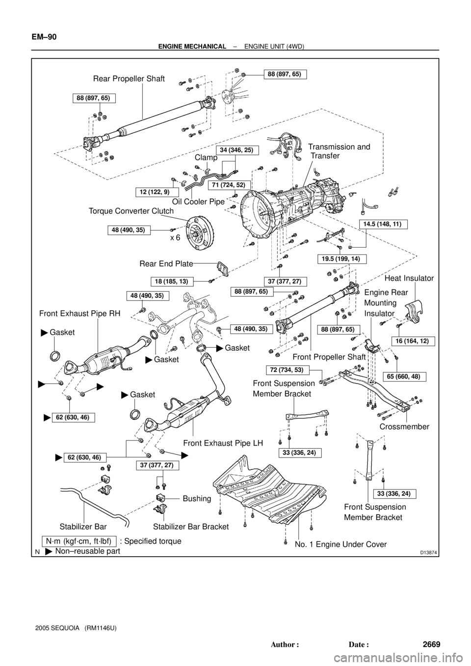
ENGINE UNIT (4WD)
COMPONENTS
Page 2676 of 4323
A08928
ECM Connector ECM and Bracket AssemblyHeater to Register Dust
Lower No.2 Finish Panel
Glove Compartment Door
Wire Harness Connector (Cassette Connector)
A23366
Engine Wire Clamp
Engine WireHeater Hose Ground Strap
Fuel Inlet
HoseBattery
Negative
(±) Cable Heater Hose
Fuel Return
Hose
Generator Wire
Battery
Positive (+)
Terminal Clamp
Generator
Connector
EVAP Hose
w/o Hydraulic Brake Booster:
Brake Booster Tube
± ENGINE MECHANICALENGINE UNIT (4WD)
EM±89
2668 Author�: Date�:
2005 SEQUOIA (RM1146U)
Page 2677 of 4323
D13874
N´m (kgf´cm, ft´lbf) : Specified torque
�Non±reusable part
37 (377, 27)
Stabilizer Bar
Bushing
Stabilizer Bar Bracket
No. 1 Engine Under Cover
18 (185, 13)
Rear End Plate
Torque Converter Clutch
x 6
48 (490, 35)
Oil Cooler Pipe
34 (346, 25)
Gasket �
Front Exhaust Pipe RH
48 (490, 35)
Gasket �
� Gasket
37 (377, 27)
Crossmember
Engine Rear
Mounting
Insulator
19.5 (199, 14)
14.5 (148, 11)
Transmission and
Transfer
88 (897, 65)
Rear Propeller Shaft88 (897, 65)
Front Propeller Shaft
Heat Insulator
Front Exhaust Pipe LH
Clamp
71 (724, 52)
� Gasket
48 (490, 35)
16 (164, 12)
65 (660, 48)
88 (897, 65)
88 (897, 65)
72 (734, 53)
Front Suspension
Member Bracket
33 (336, 24)
Front Suspension
Member Bracket
33 (336, 24)
��
�62 (630, 46)
�62 (630, 46)�
12 (122, 9)
EM±90
± ENGINE MECHANICALENGINE UNIT (4WD)
2669 Author�: Date�:
2005 SEQUOIA (RM1146U)
Page 2678 of 4323
B17615
Engine Unit Assembly
A/C Compressor
PS Pump
Drive Plate Oil Cooler Pipe
for Transmission
Rear Spacer Stay
Front Spacer
x 8
Stay
Stay
N´m (kgf´cm, ft´lbf) : Specified torque
See page EM±95
1st 49 (500, 36)
2nd Turn 90°
17 (175, 13)
A/C Compressor
Connector
38 (388, 28)
49 (500, 36)
38 (388, 28)
41 (420, 30)
x 6
± ENGINE MECHANICALENGINE UNIT (4WD)
EM±91
2670 Author�: Date�:
2005 SEQUOIA (RM1146U)


A23366
Engine Wire Clamp
Engine WireHeat")
 : Specified torque
See page EM±95
1")