Page 2663 of 4323
A08928
ECM Connector ECM and Bracket AssemblyHeater to Register Dust
Lower No.2 Finish Panel
Glove Compartment Door
Wire Harness Connector (Cassette Connector)
A23366
Engine Wire Clamp
Engine WireHeater Hose Ground Strap
Fuel Inlet
HoseBattery
Negative
(±) Cable Heater Hose
Fuel Return
Hose
Generator Wire
Battery
Positive (+)
Terminal Clamp
Generator
Connector
EVAP Hose
w/o Hydraulic Brake Booster:
Brake Booster Tube
EM±76
± ENGINE MECHANICALENGINE UNIT (2WD)
2655 Author�: Date�:
2005 SEQUOIA (RM1146U)
Page 2664 of 4323
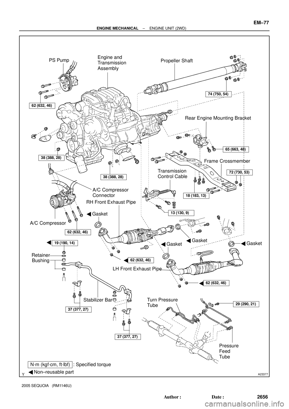
A23377
PS Pump
Propeller Shaft
A/C Compressor
Connector
Stabilizer Bar
N´m (kgf´cm, ft´lbf) : Specified torque
� Non±reusable part
A/C Compressor
Engine and
Transmission
Assembly
Frame Crossmember Rear Engine Mounting Bracket
Transmission
Control Cable
62 (632, 46)
38 (388, 28)
65 (663, 48)
18 (183, 13)
13 (130, 9)
62 (632, 46)
� Gasket
38 (388, 28)
74 (750, 54)
Turn Pressure
Tube
Pressure
Feed
Tube
RH Front Exhaust Pipe
72 (730, 53)
LH Front Exhaust Pipe
� Gasket� Gasket� Gasket
37 (377, 27)
19 (190, 14)�
37 (377, 27)
Retainer
Bushing
29 (290, 21)
62 (632, 46)�
62 (632, 46)�
± ENGINE MECHANICALENGINE UNIT (2WD)
EM±77
2656 Author�: Date�:
2005 SEQUOIA (RM1146U)
Page 2665 of 4323
A17676
Oil Cooler Pipe for Transmission
Oil Dipstick and Guide
for Transmission
Engine Unit Assembly
Front Spacer
Flywheel Housing Under CoverRear Spacer
Drive Plate � O±Ring
48 (490, 35)
x 8
x 6
N´m (kgf´cm, ft´lbf) : Specified torque
� Non±reusable part
� Precoated part��
Clamp
Stay
StayStay
See page EM±83
1st 49 (500, 36)
2nd Turn 90°
Transmission
(with Torque
Converter Clutch)
x 10
37 (380, 27) for 14 mm Head
72 (730, 53) for 17 mm Head
Connector
Connector
Connector
18 (183, 13)
EM±78
± ENGINE MECHANICALENGINE UNIT (2WD)
2657 Author�: Date�:
2005 SEQUOIA (RM1146U)
Page 2666 of 4323

EM±79
2658 Author�: Date�:
2005 SEQUOIA (RM1146U)
REMOVAL
1. REMOVE ENGINE HOOD
2. REMOVE ENGINE UNDER COVER
3. DISCONNECT BATTERY")
EM120±07
B07536
Disconnect
± ENGINE MECHANICALENGINE UNIT (2WD)
EM±79
2658 Author�: Date�:
2005 SEQUOIA (RM1146U)
REMOVAL
1. REMOVE ENGINE HOOD
2. REMOVE ENGINE UNDER COVER
3. DISCONNECT BATTERY CABLES
(a) Disconnect the clamp on battery negative (±) cable from
the No.2 relay box.
(b) Disconnect the battery positive (+) terminal cable.
(c) Disconnect battery negative (±) cable from the left fender
apron.
4. DRAIN ENGINE COOLANT
5. REMOVE RADIATOR ASSEMBLY (See page CO±17)
6. REMOVE THROTTLE BODY COVER
7. REMOVE AIR CLEANER AND INTAKE AIR CONNEC-
TOR ASSEMBLY
(a) Disconnect the MAF meter connector.
(b) Loosen the 3 bolts, and remove the air cleaner case.
(c) Remove the suction hose from the intake air connector.
(d) Disconnect the PS air hose, air inlet hose for EVAP, PCV
hose and MAF meter wire from the air intake connector.
(e) Disconnect the intake air connector from the throttle body.
8. REMOVE DRIVE BELT, FAN, FLUID COUPLING AND
FAN PULLEY
(a) Loosen the 4 nuts holding the fluid coupling to the fan
bracket.
(b) Remove the drive belt. (See page CH±7)
(c) Remove the 4 nuts, the fan, fluid coupling assembly and
fan pulley.
9. DISCONNECT ENGINE WIRE FROM CABIN
(a) Remove the glove compartment door.
(b) Remove the lower No.2 panel.
(c) Remove the 3 screws, and disconnect the ECM from the
body bracket.
(d) Disconnect the 3 wire harness connectors from the ECM.
(e) Disconnect the 2 wire harness connectors (cassette con-
nector).
(f) Disconnect the engine wire from the engine wire bracket
and remove the bolt, 2 nuts and bracket.
(g) Pull out the engine wire from the cowl panel.
10. DISCONNECT HOSES, WIRES, CONNECTORS,
CLAMPS, GROMMET AND CABLES
(a) Disconnect the 2 PS air hoses from hose clamp on the
No.3 RH timing belt cover.
(b) Disconnect the generator wire.
(c) Disconnect the generator connector.
Page 2667 of 4323

2659 Author�: Date�:
2005 SEQUOIA (RM1146U)
(d) Disconnect the hose clamp for the PS air hose.
(e) Disconnect the PS air hose from")
A09151
A08905
A08907
EM±80
± ENGINE MECHANICALENGINE UNIT (2WD)
2659 Author�: Date�:
2005 SEQUOIA (RM1146U)
(d) Disconnect the hose clamp for the PS air hose.
(e) Disconnect the PS air hose from the upper intake man-
ifold.
(f) Disconnect the 2 heater hoses.
(g) Disconnect the ground strap from the cowl panel.
(h) Disconnect the fuel inlet hose and clamps.
(i) Disconnect the fuel return hose and clamp.
(j) Disconnect the air inlet hose from the charcoal canister.
(k) Disconnect the EVAP hose from the charcoal canister.
(l) w/o Hydraulic brake booster:
Disconnect the brake booster tube.
11. REMOVE FRONT EXHAUST PIPES
(See page EM±126)
12. REMOVE PROPELLER SHAFT (See page PR±3)
13. REMOVE FRONT STABILIZER BAR
(See page SA±91)
14. DISCONNECT POWER STEERING GEAR PIPES
Disconnect the pressure feed tube, turn tube and pressure
tubes from the PS gear assembly.
(See page SR±40, SR±41)
15. REMOVE TRANSMISSION CONTROL CABLE
(a) Remove the 2 bolts and control cable bracket from the
transmission.
(b) Remove the control cable from the control shift lever.
16. DISCONNECT A/C COMPRESSOR FROM ENGINE
(a) Disconnect the A/C compressor connector.
(b) Remove the 3 bolts, and disconnect the A/C compressor
from the engine.
HINT:
Suspend the A/C compressor securely.
17. DISCONNECT PS PUMP FROM ENGINE
Remove the 3 bolts, and disconnect the PS pump from the en-
gine.
HINT:
Suspend the PS pump securely.
Page 2668 of 4323

EM±81
2660 Author�: Date�:
2005 SEQUOIA (RM1146U)
18. REMOVE ENGINE MOUNTING BRACKETS
(a) Attach the engine chain hoist t")
A09147
A08804
A08906
A08805
Lift
Down
± ENGINE MECHANICALENGINE UNIT (2WD)
EM±81
2660 Author�: Date�:
2005 SEQUOIA (RM1146U)
18. REMOVE ENGINE MOUNTING BRACKETS
(a) Attach the engine chain hoist to the engine hangers.
(b) Remove the 4 nuts and 4 bolts holding the engine mount-
ing brackets to the frame brackets.
19. PLACE JACK UNDER TRANSMISSION
20. REMOVE ENGINE REAR MOUNTING BRACKET
(a) Remove the 8 bolts, 2 nuts and frame crossmember.
(b) Remove the 4 bolts and engine rear mounting bracket
from the transmission.
21. REMOVE ENGINE AND TRANSMISSION ASSEMBLY
FROM VEHICLE
(a) Lift the engine out of the vehicle slowly and carefully.
HINT:
Make sure the engine is clear of all wiring, hoses and cables.
(b) Place the engine and transmission assembly onto the
stand.
22. DISCONNECT ENGINE WIRE FROM TRANSMISSION
(a) Disconnect the 5 connectors.
(b) Disconnect the 2 wire clamps.
23. REMOVE OIL DIPSTICK GUIDE AND DIPSTICK FOR
TRANSMISSION
(a) Disconnect the 2 breather hoses from the dipstick guide.
(b) Remove the 2 bolts.
(c) Pull out the dipstick guide and dipstick from the dipstick
tube of transmission.
(d) Remove the O±ring from the dipstick guide.
24. REMOVE OIL COOLER PIPES FOR TRANSMISSION
(a) Remove the 3 bolts and 3 stays.
Page 2669 of 4323
A15637
A08900
A08901
A04857
EM±82
± ENGINE MECHANICALENGINE UNIT (2WD)
2661 Author�: Date�:
2005 SEQUOIA (RM1146U)
(b) Loosen the 2 union nuts, and remove the 2 oil cooler
pipes.
25. REMOVE TORQUE CONVERTER CLUTCH BOLTS
(a) Remove the bolt and flywheel housing under cover.
(b) Turn the crankshaft pulley bolt to gain access to each bolt.
(c) Hold the crankshaft pulley bolt with a wrench, and remove
the 6 bolts.
26. REMOVE TRANSMISSION
(a) Remove the 10 bolts.
(b) Remove the transmission together with the torque con-
verter clutch from the engine.
27. REMOVE DRIVE PLATE
Remove the 8 bolts, front spacer, drive plate and rear spacer.
Page 2670 of 4323

EM±83
2662 Author�: Date�:
2005 SEQUOIA (RM1146U)
INSTALLATION
1. INSTALL")
EM121±07
A04869
Adhesive
A04857
1
2
3
47
6
8
5
A05137
Painted
Mark
90°
90°
A08901
± ENGINE MECHANICALENGINE UNIT (2WD)
EM±83
2662 Author�: Date�:
2005 SEQUOIA (RM1146U)
INSTALLATION
1. INSTALL DRIVE PLATE
HINT:
�The mounting bolts are tightened in 2 progressive steps
(steps (c) and (e)).
�If any one of the mounting bolts is broken or deformed, re-
place it.
(a) Apply adhesive to 2 or 3 threads of the mounting bolt end.
Adhesive:
Part No. 08833±00070, THREE BOND 1324 or equiva-
lent
(b) Install the front spacer, drive plate and rear spacer on the
crankshaft.
(c) Install and uniformly tighten the 8 mounting bolts in sever-
al passes, in the sequence shown.
Torque: 49 N´m (500 kgf´cm, 36 ft´lbf)
If any one of the mounting bolts does not meet the torque speci-
fication, replace the mounting bolt.
(d) Mark the mounting bolt with paint.
(e) Retighten the mounting bolts by 90° in the numerical or-
der shown.
(f) Check that the painted mark is now at a 90° angle to (e).
2. INSTALL TRANSMISSION TO ENGINE
(a) Check the torque converter clutch installation.
(See page AT±29)
(b) Attach the transmission to the engine.
(c) Install the 10 bolts.
Torque:
37 N´m (380 kgf´cm, 27 ft´lbf) for 14 mm head
72 N´m (730 kgf´cm, 53 ft´lbf) for 17 mm head

A23366
Engine Wire Clamp
Engine WireHeat")