Page 2014 of 4323
DI±1812
± DIAGNOSTICSDRIVER DOOR CONTROL SYSTEM
2006 Author�: Date�:
2005 SEQUOIA (RM1146U)
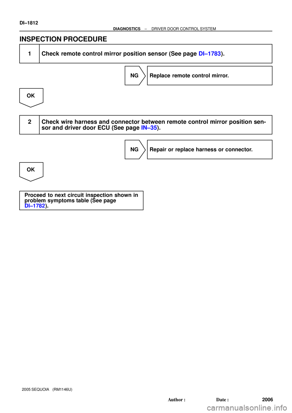
INSPECTION PROCEDURE
1 Check remote control mirror position sensor (See page DI±1783).
NG Replace remote control mirror.
OK
2 Check wire harness and connector between remote control mirror position sen-
sor and driver door ECU (See page IN±35).
NG Repair or replace harness or connector.
OK
Proceed to next circuit inspection shown in
problem symptoms table (See page
DI±1782).
Page 2015 of 4323

Power window master switch circuit
CIRCUIT DESCRIPTION
The power window master switch circuit can be che")
± DIAGNOSTICSDRIVER DOOR CONTROL SYSTEM
DI±1813
2007 Author�: Date�:
2005 SEQUOIA (RM1146U)
Power window master switch circuit
CIRCUIT DESCRIPTION
The power window master switch circuit can be checked using the DTC check (refer to DI±1904).
INSPECTION PROCEDURE
1 Check the power window master switch using hand±held tester.
PREPARATION:
(a) Connect the hand±held tester to the DLC3.
(b) Turn the ignition switch ON.
CHECK:
According to the display on the tester, read the DATA LIST.
D±DOOR:
ItemMeasurement Item/Dis-
play (Range)Normal ConditionDiagnostic Note
D P/W AUTO SWP/W auto SW signal/
ON or OFFON: P/W auto UP/DOWN SW is ON
OFF: P/W auto UP/DOWN SW is OFF±
P P/W AUTO SWP/W auto SW signal/
ON or OFFON: P/W auto UP/DOWN SW is ON
OFF: P/W auto UP/DOWN SW is OFF±
OK:
Indication on the tester switches between ON and OFF in accordance with the window auto up
operation status.
OK Proceed to next circuit inspection shown in
problem symptoms table (See page DI±1782).
NG
Replace the driver door ECU.
DI94N±04
Page 2016 of 4323
DIDER±01
DI±1814
± DIAGNOSTICSPASSENGER DOOR CONTROL SYSTEM
2008 Author�: Date�:
2005 SEQUOIA (RM1146U)
PASSENGER DOOR CONTROL SYSTEM
PRECAUTION
NOTICE:
When disconnecting the battery terminal, initialize the following system after the terminal is recon-
nected.
System NameSee Page
Back Door Power Window Control SystemBE±77
Page 2018 of 4323
DI1PP±07
Customer Problem Analysis
Vehicle Brought to Workshop
Problem Symptom ConfirmationSymptom Simulation Symptom does not
occur
Circuit Inspection
Identification of Problem
Repair
Confirmation Test
EndTitles inside
are titles of pages in this
manual, with the page number indicated in
the bottom portion. See the indicated pages
for detailed explanations.
1
23
65
8P. IN±24
P. DI±1904 P. DI±1817
P. DI±1826 ± DI±1849
Symptom
occurs
Step 6, 8: Diagnostic steps permitting use of the
hand±held tester. 7
Multiplex Communication System Inspection * 4
Problem Symptoms Table
P. DI±1818
*: Confirm that there is no trouble by
DTC check.
DI±1816
± DIAGNOSTICSPASSENGER DOOR CONTROL SYSTEM
2010 Author�: Date�:
2005 SEQUOIA (RM1146U)
HOW TO PROCEED WITH TROUBLESHOOTING
HINT:
This ECU is connected to the multiplex communication system. Therefore, be sure to check that there is no
trouble in the multiplex communication system before performing the troubleshooting.
Page 2020 of 4323

PROBLEM SYMPTOMS TABLE
POWER WINDOW CONTROL SYSTEM
SymptomSuspected AreaSee page
Power wind")
DI1PV±06
DI±1818
± DIAGNOSTICSPASSENGER DOOR CONTROL SYSTEM
2012 Author�: Date�:
2005 SEQUOIA (RM1146U)
PROBLEM SYMPTOMS TABLE
POWER WINDOW CONTROL SYSTEM
SymptomSuspected AreaSee page
Power window does not operate.
1. Power source circuit
2. Power window motor circuit
3. Window lock switch circuit
4. Passenger door ECUDI±1826
DI±1836
DI±1843
IN±35
Auto up (or down) function does not operate.1. Power source circuit
2. Passenger door ECUDI±1826
IN±35
Jam protection function and auto up (or down) function do not
operate.1. Jam protection limit switch circuit
2. Jam protection pulse sensor circuit
3. Passenger door ECUDI±1838
DI±1841
IN±35
OTHER
SymptomSuspected AreaSee page
Door parts do not function.1. Power source circuit
2. Passenger door ECUDI±1826
IN±35
Door key related function does not operate.1. Door key lock and unlock switch circuit
2. Passenger door ECUDI±1832
IN±35
Courtesy light does not come on.
(Passenger's)1. Door courtesy light circuit
2. Passenger door ECUDI±1834
IN±35
Remote control mirror RH does not operate.
(w/ Driving position memory)1. Remote control mirror motor RH circuit
2. Remote control mirror position sensor RH circuit
3. Passenger door ECUDI±1845
DI±1847
IN±35
Door lock control does not operate.
1. Door unlock detection switch circuit
2. Door lock motor circuit
3. Passenger door ECUDI±1829
DI±1720
IN±35
Page 2029 of 4323
± DIAGNOSTICSPASSENGER DOOR CONTROL SYSTEM
DI±1827
2021 Author�: Date�:
2005 SEQUOIA (RM1146U)
INSPECTION PROCEDURE
1 Check ECU±IG, AM1, PWR No. 5 and ECU±B fuse.
CHECK:
Check continuity of the ECU±IG, AM1, PWR No. 5 and ECU±B fuse.
OK:
Continuity
NG Replace the faulty fuse.
OK
2 Check voltage between terminals BDR, CPUB, SIG and GND of passenger door
ECU connector.
PREPARATION:
Turn the ignition switch ON.
CHECK:
Measure the voltage between terminals SIG and GND of the passenger door ECU of the wire harness side
connector.
OK:
Voltage: 10 to 14 V
PREPARATION:
(a) Turn the ignition switch OFF.
(b) Disconnect the passenger door ECU connector.
CHECK:
Measure the voltage between terminals BDR, CPUB and GND of the passenger door ECU of the wire har-
ness side connector.
OK:
Voltage: 10 to 14 V
OK Proceed to next circuit inspection shown in
problem symptoms table (See page DI±1818).
NG
Page 2030 of 4323
DI±1828
± DIAGNOSTICSPASSENGER DOOR CONTROL SYSTEM
2022 Author�: Date�:
2005 SEQUOIA (RM1146U)
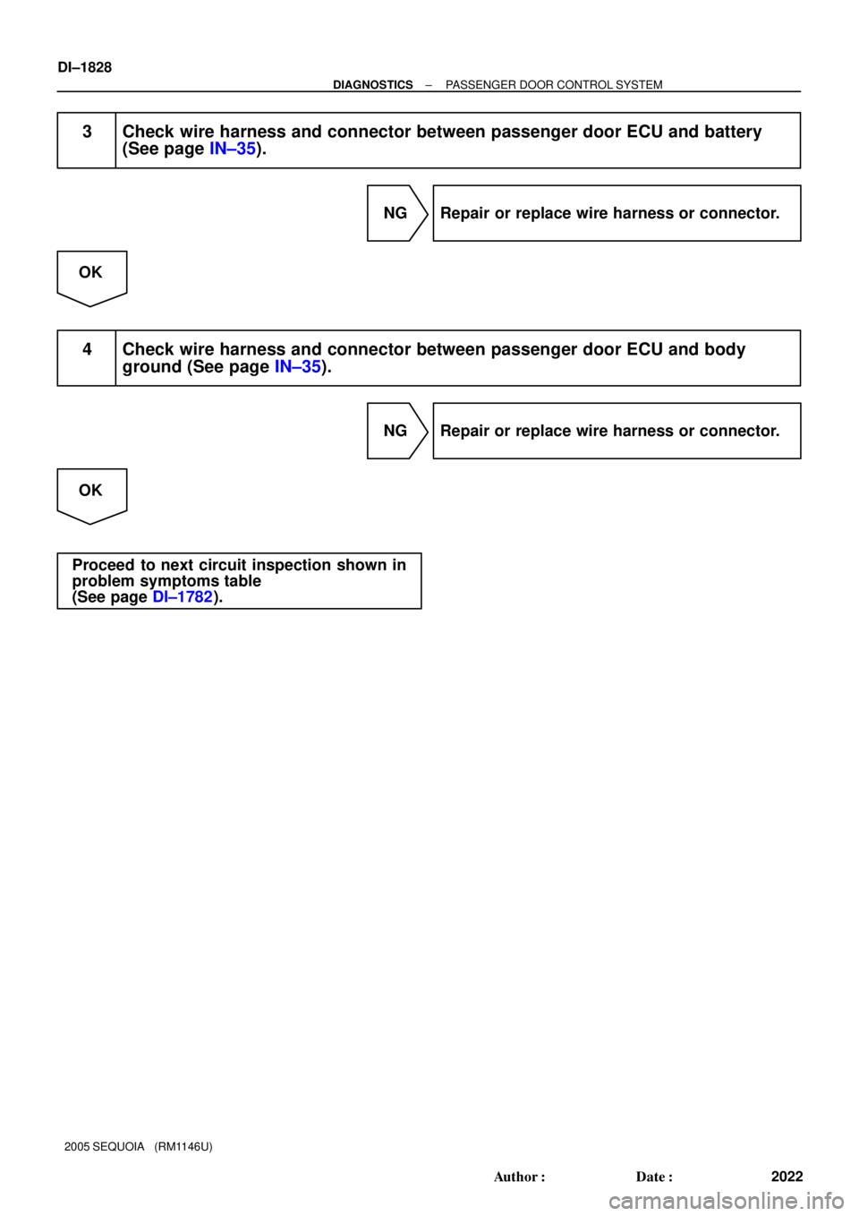
3 Check wire harness and connector between passenger door ECU and battery
(See page IN±35).
NG Repair or replace wire harness or connector.
OK
4 Check wire harness and connector between passenger door ECU and body
ground (See page IN±35).
NG Repair or replace wire harness or connector.
OK
Proceed to next circuit inspection shown in
problem symptoms table
(See page DI±1782).
Page 2032 of 4323
DI±1830
± DIAGNOSTICSPASSENGER DOOR CONTROL SYSTEM
2024 Author�: Date�:
2005 SEQUOIA (RM1146U)
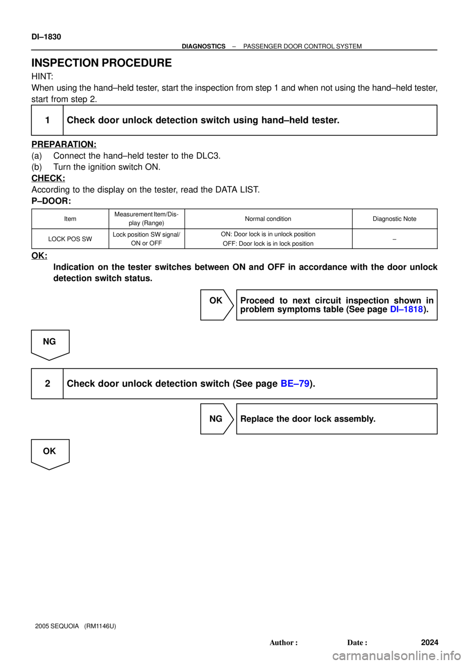
INSPECTION PROCEDURE
HINT:
When using the hand±held tester, start the inspection from step 1 and when not using the hand±held tester,
start from step 2.
1 Check door unlock detection switch using hand±held tester.
PREPARATION:
(a) Connect the hand±held tester to the DLC3.
(b) Turn the ignition switch ON.
CHECK:
According to the display on the tester, read the DATA LIST.
P±DOOR:
ItemMeasurement Item/Dis-
play (Range)Normal conditionDiagnostic Note
LOCK POS SWLock position SW signal/
ON or OFFON: Door lock is in unlock position
OFF: Door lock is in lock position±
OK:
Indication on the tester switches between ON and OFF in accordance with the door unlock
detection switch status.
OK Proceed to next circuit inspection shown in
problem symptoms table (See page DI±1818).
NG
2 Check door unlock detection switch (See page BE±79).
NG Replace the door lock assembly.
OK