Page 1980 of 4323
DIDEI±01
DI±1778
± DIAGNOSTICSDRIVER DOOR CONTROL SYSTEM
1972 Author�: Date�:
2005 SEQUOIA (RM1146U)
DRIVER DOOR CONTROL SYSTEM
PRECAUTION
NOTICE:
When disconnecting the battery terminal, initialize the following system after the terminal is recon-
nected.
System NameSee Page
Back Door Power Window Control SystemBE±77
Page 1982 of 4323
DI1P8±07
Customer Problem Analysis
Vehicle Brought to Workshop
Problem Symptom ConfirmationSymptom Simulation Symptom does not
occur
Circuit Inspection
Identification of Problem
Repair
Confirmation Test
EndTitles inside
are titles of pages in this
manual, with the page number indicated in
the bottom portion. See the indicated pages
for detailed explanations.
1
23
65
8P. IN±24
P. DI±1904 P. DI±1781
P. DI±1788 ± DI±1813
Symptom
occurs
Step 6, 8: Diagnostic steps permitting use of the hand±held tester. 7
Multiplex Communication System Inspection * 4
Problem Symptoms Table
P. DI±1782
*: Confirm that there is no trouble by
DTC check.
DI±1780
± DIAGNOSTICSDRIVER DOOR CONTROL SYSTEM
1974 Author�: Date�:
2005 SEQUOIA (RM1146U)
HOW TO PROCEED WITH TROUBLESHOOTING
HINT:
This ECU is connected to the multiplex communication system. Therefore, be sure to check that there is no
trouble in the multiplex communication system before performing the troubleshooting.
Page 1984 of 4323

PROBLEM SYMPTOMS TABLE
POWER WINDOW CONTROL SYSTEM
SymptomSuspected AreaSee page
All the power")
DI1PC±06
DI±1782
± DIAGNOSTICSDRIVER DOOR CONTROL SYSTEM
1976 Author�: Date�:
2005 SEQUOIA (RM1146U)
PROBLEM SYMPTOMS TABLE
POWER WINDOW CONTROL SYSTEM
SymptomSuspected AreaSee page
All the power windows do not operate.
4. Power source circuit
5. Window lock switch circuit
6. Body ECUDI±1788
DI±1805
IN±35
Power window does not operate.
1. Power source circuit
2. Power window motor circuit
3. Window lock switch circuit
4. Driver door ECUDI±1788
DI±1798
DI±1805
IN±35
Auto up (or down) function does not operate.1. Power source circuit
2. Driver door ECUDI±1788
IN±35
Jam protection function and auto up (or down) function do not
operate.1. Jam protection limit switch circuit
2. Jam protection pulse sensor circuit
3. Driver door ECUDI±1800
DI±1803
IN±35
OTHER
SymptomSuspected AreaSee page
Door parts do not function.1. Power source circuit
2. Driver door ECUDI±1788
IN±35
Door key related function does not operate.1. Door key lock and unlock switch circuit
2. Driver door ECUDI±1794
IN±35
Courtesy light does not come on.
(driver's)1. Door courtesy light circuit
2. Driver door ECUDI±1796
IN±35
Remote control mirror LH does not operate.
(w/ Driving position memory)1. Remote control mirror motor LH circuit
2. Remote control mirror position sensor LH circuit
3. Driver door ECUDI±1808
DI±1810
IN±35
Door lock control does not operate.
1. Door unlock detection switch circuit
2. Door lock motor circuit
3. Driver door ECUDI±1791
DI±1720
IN±35
Page 1991 of 4323
± DIAGNOSTICSDRIVER DOOR CONTROL SYSTEM
DI±1789
1983 Author�: Date�:
2005 SEQUOIA (RM1146U)
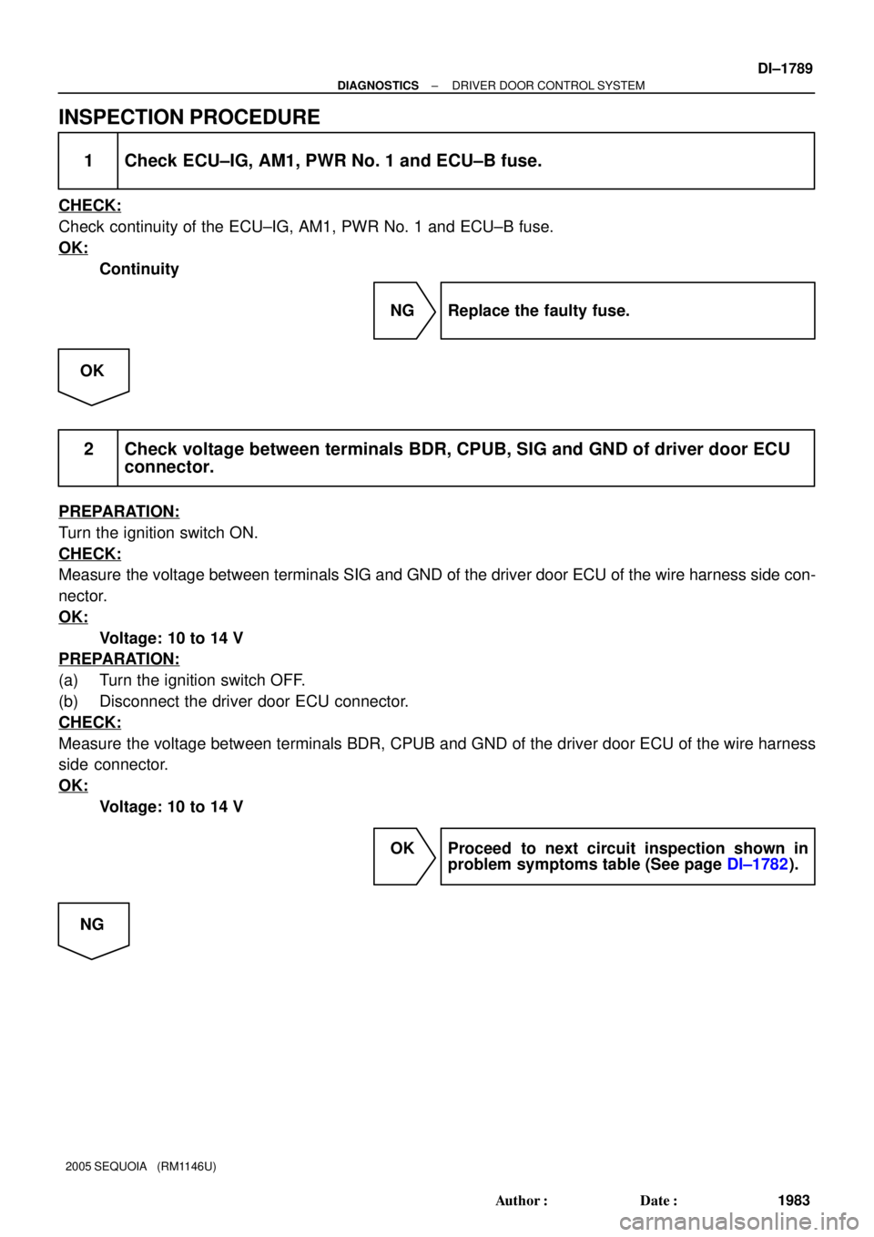
INSPECTION PROCEDURE
1 Check ECU±IG, AM1, PWR No. 1 and ECU±B fuse.
CHECK:
Check continuity of the ECU±IG, AM1, PWR No. 1 and ECU±B fuse.
OK:
Continuity
NG Replace the faulty fuse.
OK
2 Check voltage between terminals BDR, CPUB, SIG and GND of driver door ECU
connector.
PREPARATION:
Turn the ignition switch ON.
CHECK:
Measure the voltage between terminals SIG and GND of the driver door ECU of the wire harness side con-
nector.
OK:
Voltage: 10 to 14 V
PREPARATION:
(a) Turn the ignition switch OFF.
(b) Disconnect the driver door ECU connector.
CHECK:
Measure the voltage between terminals BDR, CPUB and GND of the driver door ECU of the wire harness
side connector.
OK:
Voltage: 10 to 14 V
OK Proceed to next circuit inspection shown in
problem symptoms table (See page DI±1782).
NG
Page 1992 of 4323
DI±1790
± DIAGNOSTICSDRIVER DOOR CONTROL SYSTEM
1984 Author�: Date�:
2005 SEQUOIA (RM1146U)
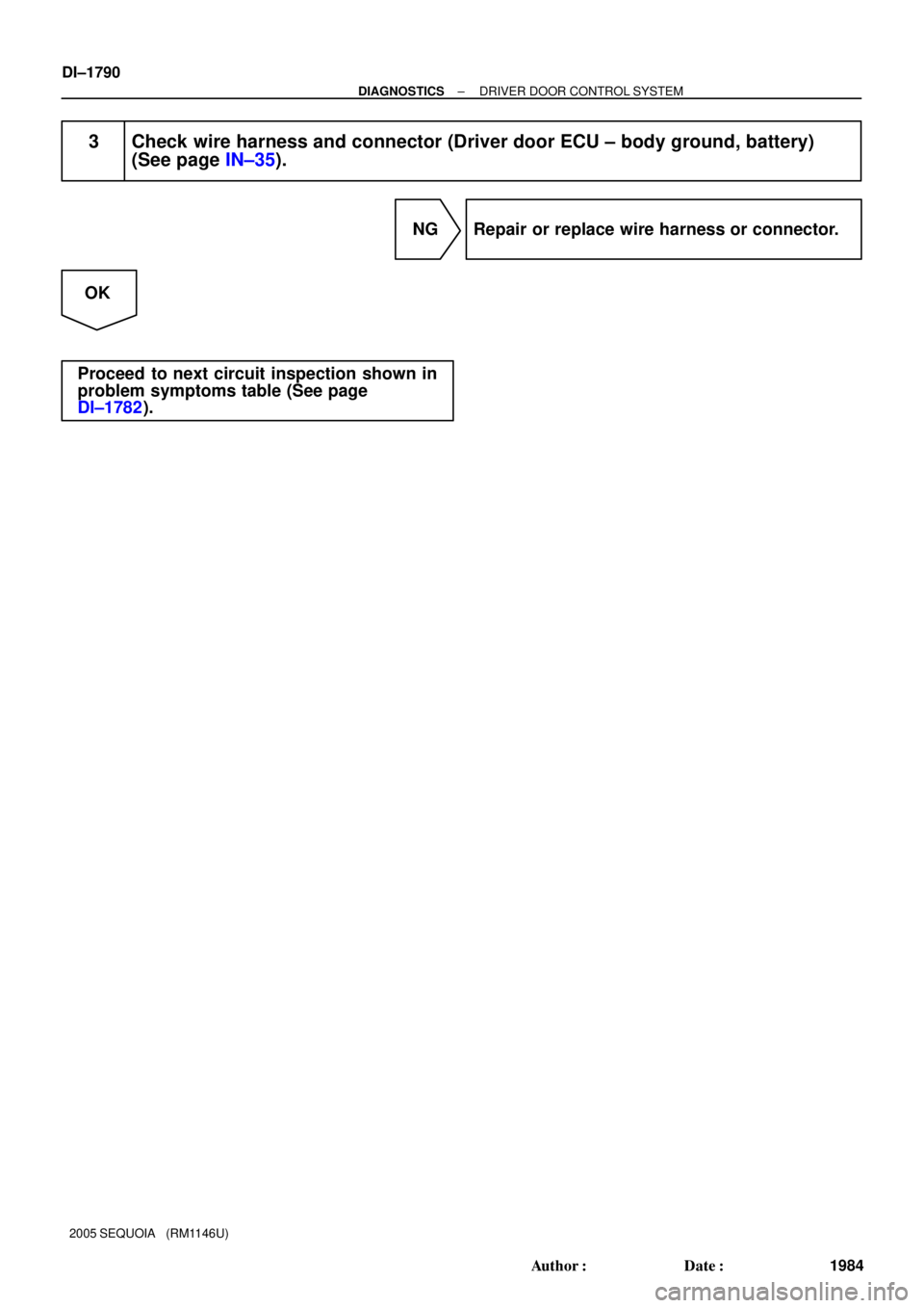
3 Check wire harness and connector (Driver door ECU ± body ground, battery)
(See page IN±35).
NG Repair or replace wire harness or connector.
OK
Proceed to next circuit inspection shown in
problem symptoms table (See page
DI±1782).
Page 1994 of 4323
DI±1792
± DIAGNOSTICSDRIVER DOOR CONTROL SYSTEM
1986 Author�: Date�:
2005 SEQUOIA (RM1146U)
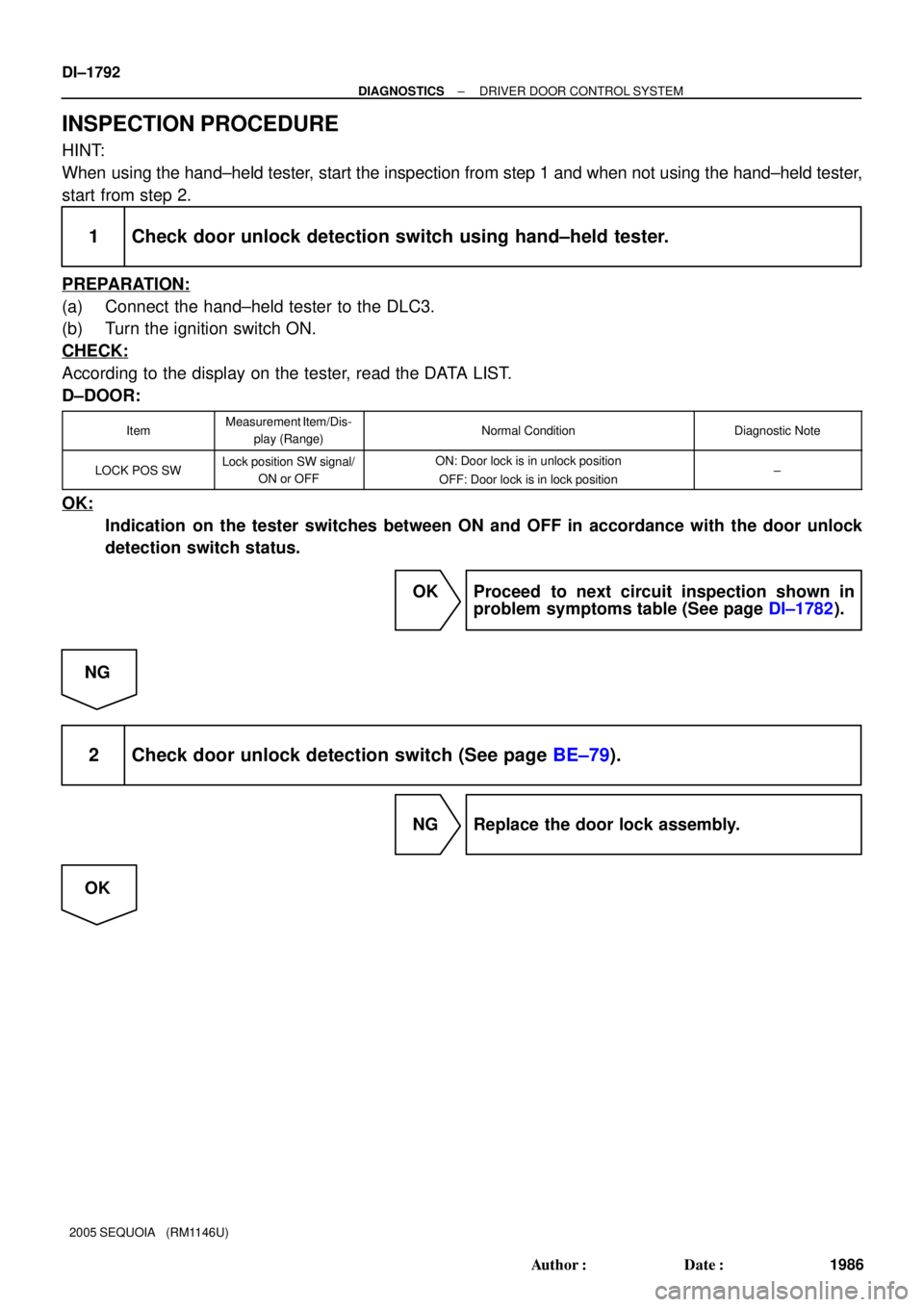
INSPECTION PROCEDURE
HINT:
When using the hand±held tester, start the inspection from step 1 and when not using the hand±held tester,
start from step 2.
1 Check door unlock detection switch using hand±held tester.
PREPARATION:
(a) Connect the hand±held tester to the DLC3.
(b) Turn the ignition switch ON.
CHECK:
According to the display on the tester, read the DATA LIST.
D±DOOR:
ItemMeasurement Item/Dis-
play (Range)Normal ConditionDiagnostic Note
LOCK POS SWLock position SW signal/
ON or OFFON: Door lock is in unlock position
OFF: Door lock is in lock position±
OK:
Indication on the tester switches between ON and OFF in accordance with the door unlock
detection switch status.
OK Proceed to next circuit inspection shown in
problem symptoms table (See page DI±1782).
NG
2 Check door unlock detection switch (See page BE±79).
NG Replace the door lock assembly.
OK
Page 1995 of 4323
± DIAGNOSTICSDRIVER DOOR CONTROL SYSTEM
DI±1793
1987 Author�: Date�:
2005 SEQUOIA (RM1146U)
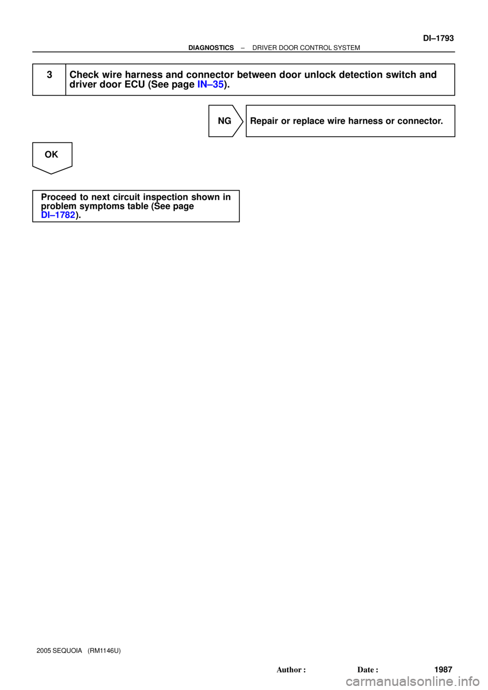
3 Check wire harness and connector between door unlock detection switch and
driver door ECU (See page IN±35).
NG Repair or replace wire harness or connector.
OK
Proceed to next circuit inspection shown in
problem symptoms table (See page
DI±1782).
Page 1997 of 4323
± DIAGNOSTICSDRIVER DOOR CONTROL SYSTEM
DI±1795
1989 Author�: Date�:
2005 SEQUOIA (RM1146U)
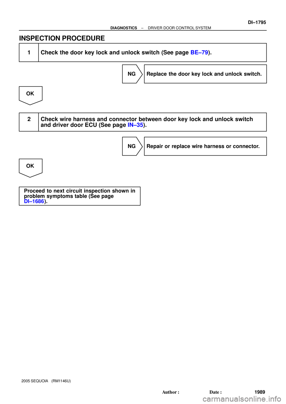
INSPECTION PROCEDURE
1 Check the door key lock and unlock switch (See page BE±79).
NG Replace the door key lock and unlock switch.
OK
2 Check wire harness and connector between door key lock and unlock switch
and driver door ECU (See page IN±35).
NG Repair or replace wire harness or connector.
OK
Proceed to next circuit inspection shown in
problem symptoms table (See page
DI±1686).