Page 1940 of 4323
DI±1738
± DIAGNOSTICSBODY CONTROL SYSTEM
1932 Author�: Date�:
2005 SEQUOIA (RM1146U)
INSPECTION PROCEDURE
1 Check that DTC B1242 is not indicated (See page DI±1829).
OK:
DTC B1242 is not indicated.
NG Go to multiplex communication system
(See page DI±1892).
OK
2 Check wire harness and connector (PRG circuit).
PREPARATION:
Disconnect the connectors of the wireless door lock receiver and body ECU.
CHECK:
Check continuity between terminal W2±3 (PRG) of the wireless door lock receiver and terminal B5±5 (PRG)
of the body ECU.
OK:
Continuity
NG Repair or replace wire harness or connector.
OK
3 Check voltage between terminals +B and E of wireless door lock receiver.
CHECK:
Measure the voltage between terminals W2±5 (+B) and W2±1 (E) of the wireless door lock receiver.
OK:
Voltage: 10 to 14 V
NG Repair or replace harness or connector.
OK
Page 1941 of 4323

4 Check wireless door lock receiver.
PREPARATION:
Check that malfunction disappears when another wireless door")
± DIAGNOSTICSBODY CONTROL SYSTEM
DI±1739
1933 Author�: Date�:
2005 SEQUOIA (RM1146U)
4 Check wireless door lock receiver.
PREPARATION:
Check that malfunction disappears when another wireless door lock receiver in good condition is installed.
CHECK:
Check wireless door lock function.
OK:
The wireless door lock system operates normally.
NG Proceed to next circuit inspection shown in
problem symptoms table (See page DI±1686).
OK
Failure of the original wireless door lock re-
ceiver.
5 Check wire harness and connector (RDA circuit).
PREPARATION:
Disconnect the wireless door lock receiver connector.
CHECK:
Check continuity between terminal W2±2 (RDA) of the wireless door lock receiver and terminal B5±4 (RDA)
of the body ECU.
OK:
Continuity
NG Repair or replace harness or connector.
OK
6 Check voltage between terminals +B and E of wireless door lock receiver.
CHECK:
Measure the voltage between terminals W2±5 (+B) and W2±1 (E) of the wireless door lock receiver.
OK:
Voltage: 10 to 14 V
NG Repair or replace harness or connector.
OK
Page 1942 of 4323
DI±1740
± DIAGNOSTICSBODY CONTROL SYSTEM
1934 Author�: Date�:
2005 SEQUOIA (RM1146U)
7 Check wireless door lock receiver.
PREPARATION:
Check that malfunction disappears when another wireless door lock receiver in good condition is installed.
CHECK:
Check wireless door lock function.
OK:
The wireless door lock system operates normally.
NG Proceed to next circuit inspection shown in
problem symptoms table (See page DI±1686).
OK
Failure of the original wireless door lock re-
ceiver.
Page 1944 of 4323
DI±1742
± DIAGNOSTICSBODY CONTROL SYSTEM
1936 Author�: Date�:
2005 SEQUOIA (RM1146U)
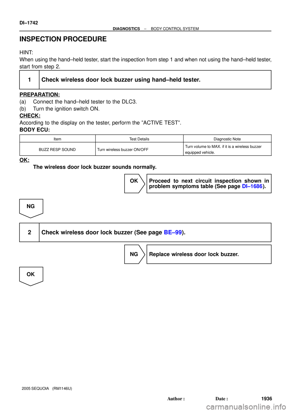
INSPECTION PROCEDURE
HINT:
When using the hand±held tester, start the inspection from step 1 and when not using the hand±held tester,
start from step 2.
1 Check wireless door lock buzzer using hand±held tester.
PREPARATION:
(a) Connect the hand±held tester to the DLC3.
(b) Turn the ignition switch ON.
CHECK:
According to the display on the tester, perform the ºACTIVE TESTº.
BODY ECU:
ItemTest DetailsDiagnostic Note
BUZZ RESP SOUNDTurn wireless buzzer ON/OFFTurn volume to MAX. if it is a wireless buzzer
equipped vehicle.
OK:
The wireless door lock buzzer sounds normally.
OK Proceed to next circuit inspection shown in
problem symptoms table (See page DI±1686).
NG
2 Check wireless door lock buzzer (See page BE±99).
NG Replace wireless door lock buzzer.
OK
Page 1945 of 4323
± DIAGNOSTICSBODY CONTROL SYSTEM
DI±1743
1937 Author�: Date�:
2005 SEQUOIA (RM1146U)
3 Check wire harness and connector between wireless door lock buzzer and body
ECU, body ground and wireless door lock buzzer (See page IN±35).
NG Repair or replace wire harness or connector.
OK
Proceed to next circuit inspection shown in
problem symptoms table
(See page DI±1686).
Page 1947 of 4323
± DIAGNOSTICSBODY CONTROL SYSTEM
DI±1745
1939 Author�: Date�:
2005 SEQUOIA (RM1146U)
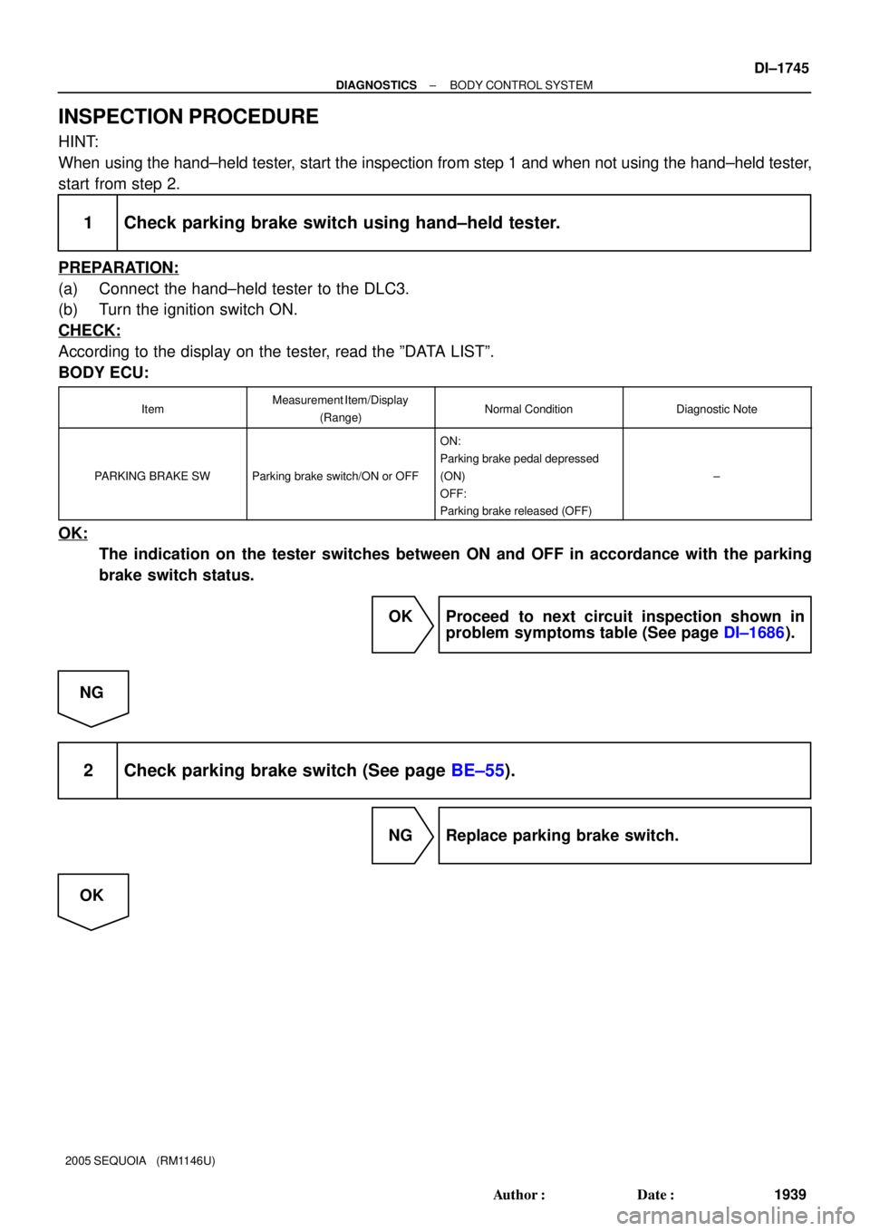
INSPECTION PROCEDURE
HINT:
When using the hand±held tester, start the inspection from step 1 and when not using the hand±held tester,
start from step 2.
1 Check parking brake switch using hand±held tester.
PREPARATION:
(a) Connect the hand±held tester to the DLC3.
(b) Turn the ignition switch ON.
CHECK:
According to the display on the tester, read the ºDATA LISTº.
BODY ECU:
ItemMeasurement Item/Display
(Range)Normal ConditionDiagnostic Note
PARKING BRAKE SWParking brake switch/ON or OFF
ON:
Parking brake pedal depressed
(ON)
OFF:
Parking brake released (OFF)
±
OK:
The indication on the tester switches between ON and OFF in accordance with the parking
brake switch status.
OK Proceed to next circuit inspection shown in
problem symptoms table (See page DI±1686).
NG
2 Check parking brake switch (See page BE±55).
NG Replace parking brake switch.
OK
Page 1948 of 4323
DI±1746
± DIAGNOSTICSBODY CONTROL SYSTEM
1940 Author�: Date�:
2005 SEQUOIA (RM1146U)
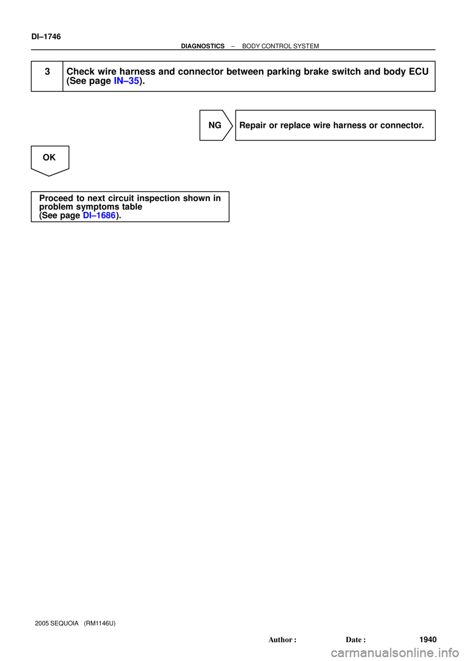
3 Check wire harness and connector between parking brake switch and body ECU
(See page IN±35).
NG Repair or replace wire harness or connector.
OK
Proceed to next circuit inspection shown in
problem symptoms table
(See page DI±1686).
Page 1950 of 4323

INSPECTION PROCEDURE
HINT:
When using the hand±held tester, start the inspection from step 1 and when not usin")
DI±1748
± DIAGNOSTICSBODY CONTROL SYSTEM
1942 Author�: Date�:
2005 SEQUOIA (RM1146U)
INSPECTION PROCEDURE
HINT:
When using the hand±held tester, start the inspection from step 1 and when not using the hand±held tester,
start from step 2.
1 Check rear power window motor using hand±held tester.
PREPARATION:
(a) Connect the hand±held tester to the DLC3.
(b) Turn the ignition switch ON.
CHECK:
According to the display on the tester, perform the ºACTIVE TESTº.
BODY ECU:
ItemTest DetailsDiagnostic Note
RL P/W UP/DOWNRear left passenger power window DOWN/UPCaution: This test causes vehicle parts to move.
Watch your hands and feet.
RR P/W UP/DOWNRear right passenger power window DOWN/UPCaution: This test causes vehicle parts to move.
Watch your hands and feet.
OK:
The rear power windows go up or down correctly when operating them through the hand±held
tester.
OK Proceed to next circuit inspection shown in
problem symptoms table (See page DI±1686).
NG
2 Check power window control switch rear (See page BE±69).
NG Replace power window switch rear.
OK
3 Check wire harness and connector between power window control switch rear
and body ECU (See page IN±35).
NG Repair or replace wire harness or connector.
OK