Page 1888 of 4323

PROBLEM SYMPTOMS TABLE
DOOR LOCK CONTROL
SymptomSuspected AreaSee page
Lock or unlock cannot be opera")
DI1OH±18
DI±1686
± DIAGNOSTICSBODY CONTROL SYSTEM
1880 Author�: Date�:
2005 SEQUOIA (RM1146U)
PROBLEM SYMPTOMS TABLE
DOOR LOCK CONTROL
SymptomSuspected AreaSee page
Lock or unlock cannot be operated with door lock control switch.
1. Door lock control switch (Power source circuit)
(Driver's)
(Passenger's)
2. Body ECU
DI±1788
DI±1826
IN±35
Door key linked function does not operate.
1. Door key lock and unlock switch circuit (Driver's)
(Passenger's)
2. Body ECUDI±1794
DI±1832
IN±35
Key confinement prevention function does not operate.1. Key unlock warning switch circuit
2. Body ECUDI±1715
IN±35
Door lock function does not operate.1. Door lock motor circuit
2. Body ECUDI±1720
IN±35
THEFT DETERRENT SYSTEM
SymptomSuspected AreaSee page
No alerting condition is operated. (The system cannot be set.)
1. Security indicator circuit
2. Key unlock warning switch circuit
3. Courtesy light switch circuit
4. Door unlock detection switch circuit (Driver's)
(Passenger's)
5. Engine hood courtesy light switch circuit
6. Back door courtesy light switch circuit
7. Back door ECU
8. Body ECUDI±1731
DI±1715
DI±1728
DI±1791
DI±1829
DI±1725
DI±1864
IN±35
IN±35
Cannot be canceled when IG is turned ON with a key.
1. Key unlock warning switch circuit
2. Ignition switch
3. Body ECUDI±1715
BE±24
IN±35
Cannot be canceled when unlocking the back door with a key.1. Back door ECU
2. Body ECUIN±35
IN±35
Headlights do not light up as an alert function.1. Headlight relay circuit
2. Body ECUDI±1708
IN±35
Taillights do not light up as an alert function.1. Taillight relay circuit
2. Body ECUDI±1706
IN±35
Theft deterrent horn or vehicle horn does not sound.
1. Security horn circuit
2. Horn circuit
3. Body ECUDI±1734
DI±1764
IN±35
During warning condition, cannot be canceled by unlocking the
door with a key.1. Door key lock and unlock switch circuit (Driver's)
(Passenger's)
2. Body ECUDI±1794
DI±1832
IN±35
During warning condition, cannot be canceled by unlocking the
door with a key. (transmitter)1. Transmitter
2. Body ECUBE±99
IN±35
During warning condition, cannot be canceled by turning the igni-
tion ON with a key.1. Ignition switch
2. Key unlock warning switch circuit
3. Body ECUBE±24
DI±1715
IN±35
The system operated for more than 60 seconds.Body ECUIN±35
Glass breakage sensor does not operate.1. Glass breakage sensor circuit
2. Body ECUDI±1774
IN±35
Page 1889 of 4323

WIRELESS DOOR LOCK CONTROL
SymptomSuspected AreaSee page
All functions of wireless door lock control system do")
± DIAGNOSTICSBODY CONTROL SYSTEM
DI±1687
1881 Author�: Date�:
2005 SEQUOIA (RM1146U)
WIRELESS DOOR LOCK CONTROL
SymptomSuspected AreaSee page
All functions of wireless door lock control system do not operate.
1. Transmitter
2. Wireless door lock receiver circuit
3. Key unlock warning switch circuit
4. Body ECUBE±99
DI±1737
DI±1715
IN±35
Lock (or unlock) function does not operate.
1. Door unlock detection switch circuit (Driver's)
(Passenger's)
(Rear Door)
(Back Door)
2. Any door ECU
3. Body ECUDI±1791
DI±1829
DI±1723
DI±1869
IN±35
IN±35
Automatic lock function operates even if any door is opened within
30 seconds after all doors are unlocked by wireless door lock
control system.1. Door courtesy light switch circuit
2. Any door ECU
3. Body ECUDI±1728
IN±35
IN±35
Wireless door lock function operates, but the buzzer does not
sound.1. Wireless door lock buzzer circuit
2. Body ECUDI±1741
IN±35
Buzzer sounds, but wireless door lock function does not operate.Body ECUIN±35
REAR WIPER AND WASHER
SymptomSuspected AreaSee page
Rear wiper does not operate.1. Rear wiper switch and motor circuit
2. Body ECUDI±1704
IN±35
Rear washer does not operate.1. Rear washer switch and motor circuit
2. Body ECUDI±1704
IN±35
LIGHT CONTROL
SymptomSuspected AreaSee page
Automatic light control does not operate.
1. Automatic light control sensor circuit
2. Light control switch circuit
3. Body ECUDI±1753
DI±1750
IN±35
Auto turn±off does not operate.
1. Door courtesy light switch circuit (Driver side)
2. Ignition switch
3. Driver door ECU
4. Body ECUDI±1728
BE±24
IN±35
IN±35
Daytime running light function does not operate.
1. Daytime running light relay circuit
2. Parking brake switch circuit
3. Body ECUDI±1712
DI±1744
IN±35
FOG LIGHT
SymptomSuspected AreaSee page
Fog lights do not come on.
1. Bulb
2. FOG fuse
3. Fog light relay and switch circuit
4. Body ECU±
BE±14
DI±1710
IN±35
OTHERS
SymptomSuspected AreaSee page
Illuminated entry function does not operate.1. Illumination circuit
2. Body ECUDI±1759
IN±35
All functions of the body control system do not operate.1. Power source circuit
2. Body ECUDI±1700
IN±35
Remote control mirror does not operate.
(w/ Driving position memory)1. Remote control mirror switch circuit
2. Driving position memory switch circuit
3. Body ECUDI±1767
DI±1772
IN±35
Page 1895 of 4323
± DIAGNOSTICSBODY CONTROL SYSTEM
DI±1693
1887 Author�: Date�:
2005 SEQUOIA (RM1146U) DOP (*2) ± GND1
(B5±9 ± B6±6)
P ± W±BGlass breakage sensor
ECU communicationArmed stateBelow 1 V
DOP (*2) ± GND1
(B5±9 ± B6±6)P ± W±BGlass breakage sensor
ECU communicationAlarm sounds (on glass break-
age detection)Pulse generation
(See page DI±1774)
(*1): w/ Daytime Running Light
(*2): w/ Glass Breakage Sensor
(*3): w/ Automatic Light Control
(*4): w/ Driving Position Memory
(*5): w/ Sliding Roof
Page 1904 of 4323
DI±1702
± DIAGNOSTICSBODY CONTROL SYSTEM
1896 Author�: Date�:
2005 SEQUOIA (RM1146U)
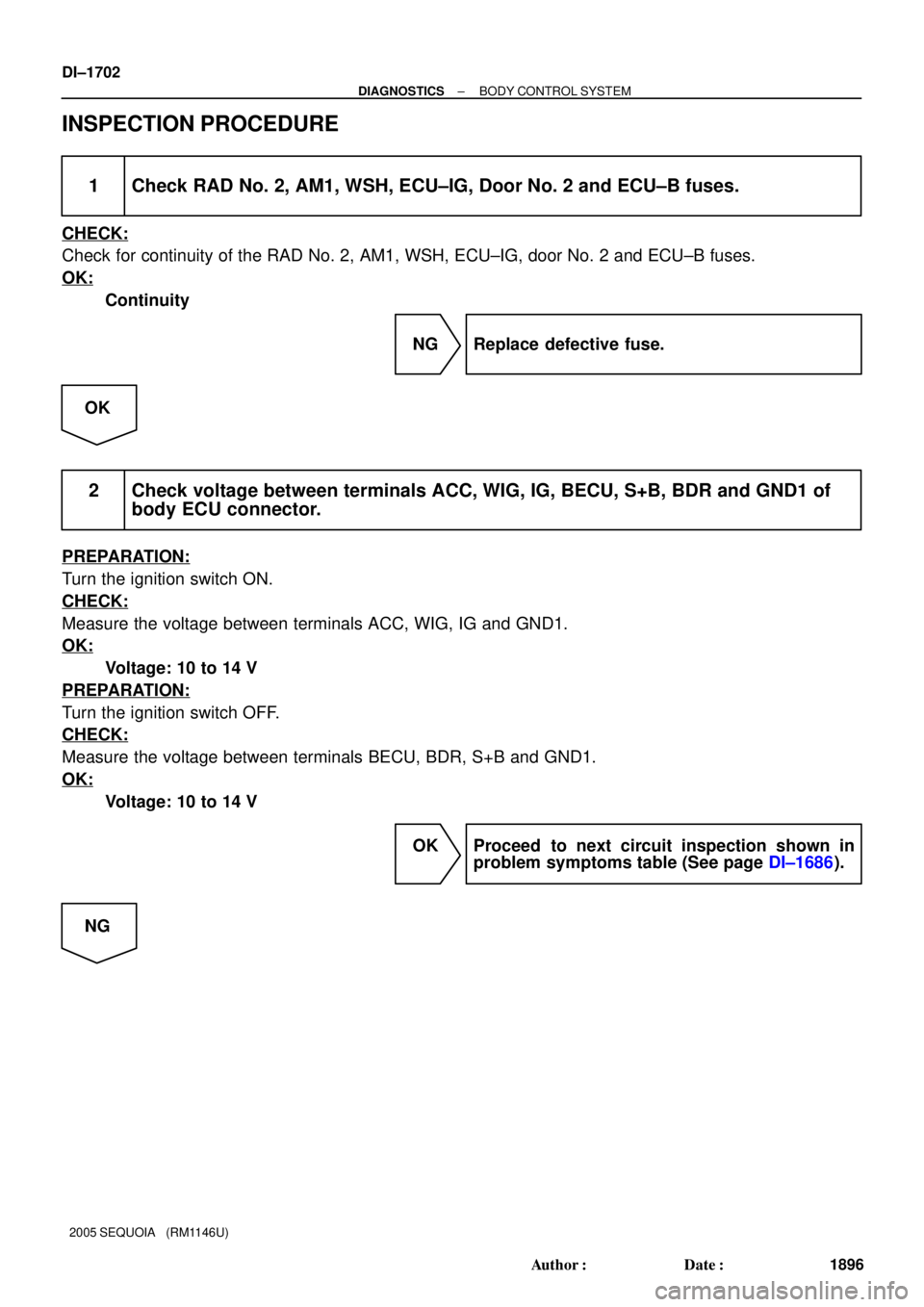
INSPECTION PROCEDURE
1 Check RAD No. 2, AM1, WSH, ECU±IG, Door No. 2 and ECU±B fuses.
CHECK:
Check for continuity of the RAD No. 2, AM1, WSH, ECU±IG, door No. 2 and ECU±B fuses.
OK:
Continuity
NG Replace defective fuse.
OK
2 Check voltage between terminals ACC, WIG, IG, BECU, S+B, BDR and GND1 of
body ECU connector.
PREPARATION:
Turn the ignition switch ON.
CHECK:
Measure the voltage between terminals ACC, WIG, IG and GND1.
OK:
Voltage: 10 to 14 V
PREPARATION:
Turn the ignition switch OFF.
CHECK:
Measure the voltage between terminals BECU, BDR, S+B and GND1.
OK:
Voltage: 10 to 14 V
OK Proceed to next circuit inspection shown in
problem symptoms table (See page DI±1686).
NG
Page 1905 of 4323
± DIAGNOSTICSBODY CONTROL SYSTEM
DI±1703
1897 Author�: Date�:
2005 SEQUOIA (RM1146U)
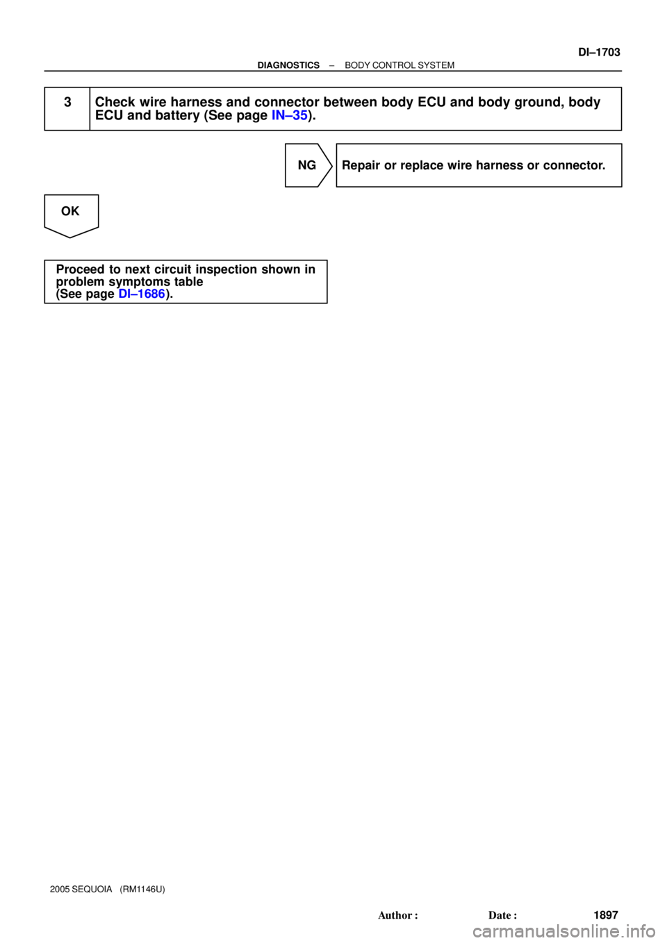
3 Check wire harness and connector between body ECU and body ground, body
ECU and battery (See page IN±35).
NG Repair or replace wire harness or connector.
OK
Proceed to next circuit inspection shown in
problem symptoms table
(See page DI±1686).
Page 1907 of 4323
± DIAGNOSTICSBODY CONTROL SYSTEM
DI±1705
1899 Author�: Date�:
2005 SEQUOIA (RM1146U)
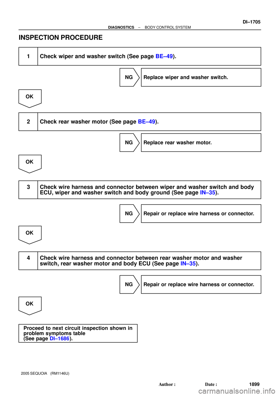
INSPECTION PROCEDURE
1 Check wiper and washer switch (See page BE±49).
NG Replace wiper and washer switch.
OK
2 Check rear washer motor (See page BE±49).
NG Replace rear washer motor.
OK
3 Check wire harness and connector between wiper and washer switch and body
ECU, wiper and washer switch and body ground (See page IN±35).
NG Repair or replace wire harness or connector.
OK
4 Check wire harness and connector between rear washer motor and washer
switch, rear washer motor and body ECU (See page IN±35).
NG Repair or replace wire harness or connector.
OK
Proceed to next circuit inspection shown in
problem symptoms table
(See page DI±1686).
Page 1909 of 4323

INSPECTION PROCEDURE
HINT:
When using the hand±held tester, start the inspection from step 1 and when not usin")
± DIAGNOSTICSBODY CONTROL SYSTEM
DI±1707
1901 Author�: Date�:
2005 SEQUOIA (RM1146U)
INSPECTION PROCEDURE
HINT:
When using the hand±held tester, start the inspection from step 1 and when not using the hand±held tester,
start from step 2.
1 Check TAILLIGHT relay using hand±held tester.
PREPARATION:
(a) Connect the hand±held tester to the DLC3.
(b) Turn the ignition switch ON.
CHECK:
According to the display on the tester, perform the ºACTIVE TESTº.
BODY ECU:
ItemTest DetailsDiagnostic Note
TAIL LIGHTTaillight ON/OFF±
OK:
The taillights turn on or off correctly when operating them through the hand±held tester.
OK Proceed to next circuit inspection shown in
problem symptoms table (See page DI±1686).
NG
2 Check TAILLIGHT relay (See page BE±27).
NG Replace TAILLIGHT relay.
OK
3 Check wire harness and connector between TAILLIGHT relay and body ECU, bat-
tery and TAILLIGHT relay (See page IN±35).
NG Repair or replace wire harness or connector.
OK
Proceed to next circuit inspection shown in
problem symptoms table
(See page DI±1686).
Page 1911 of 4323

INSPECTION PROCEDURE
HINT:
When using the hand±held tester, start the inspection from step 1 and when not usin")
± DIAGNOSTICSBODY CONTROL SYSTEM
DI±1709
1903 Author�: Date�:
2005 SEQUOIA (RM1146U)
INSPECTION PROCEDURE
HINT:
When using the hand±held tester, start the inspection from step 1 and when not using the hand±held tester,
start from step 2.
1 Check HEAD relay using hand±held tester.
PREPARATION:
(a) Connect the hand±held tester to the DLC3.
(b) Turn the ignition switch ON.
CHECK:
According to the display on the tester, perform the ºACTIVE TESTº.
BODY ECU:
ItemTest DetailsDiagnostic Note
HEAD LIGHTHeadlight relay ON/OFF±
OK:
The headlights turn on or off correctly when operating them through the hand±held tester.
OK Proceed to next circuit inspection shown in
problem symptoms table (See page DI±1686).
NG
2 Check HEAD relay (See page BE±27).
NG Replace HEAD relay.
OK
3 Check wire harness and connector between HEAD relay and body ECU, battery
and HEAD relay (See page IN±35).
NG Repair or replace wire harness or connector.
OK
Proceed to next circuit inspection shown in
problem symptoms table
(See page DI±1686).