Page 1928 of 4323

2 (±)
DI±1726
± DIAGNOSTICSBODY CONTROL SYSTEM
1920 Author�: Date�:
2005 SEQUOIA (RM1146U)
INSPECTION PROCEDURE
HINT:
When using the hand±held tester, start the inspection from step")
I00298
1 (+)
2 (±)
DI±1726
± DIAGNOSTICSBODY CONTROL SYSTEM
1920 Author�: Date�:
2005 SEQUOIA (RM1146U)
INSPECTION PROCEDURE
HINT:
When using the hand±held tester, start the inspection from step 1 and when not using the hand±held tester,
start from step 2.
1 Check engine hood courtesy switch using hand±held tester.
PREPARATION:
(a) Connect the hand±held tester to the DLC3.
(b) Turn the ignition switch ON.
CHECK:
According to the display on the tester, read the ºDATA LISTº.
BODY ECU:
ItemMeasurement Item/Display
(Range)Normal ConditionDiagnostic Note
HOOD COURTSY SWHood courtesy switch/ON or OFF
ON: Engine hood OPEN
(Hood courtesy switch ON)
OFF: Engine hood CLOSE
(Hood courtesy switch OFF)
±
OK:
The indication on the tester switches between ON and OFF in accordance with the engine hood
courtesy switch status.
OK Proceed to next circuit inspection shown in
problem symptoms table (See page DI±1686).
NG
2 Check engine hood courtesy switch.
PREPARATION:
Disconnect the engine hood courtesy switch connector.
CHECK:
Check continuity between terminals 1 and 2 when the engine
hood lock is locked and unlocked.
OK:
Engine hood lock
conditionTester connectionSpecified condition
LOCK1 ± 2No continuity
UNLOCK1 ± 2Continuity
NG Replace engine hood courtesy switch.
OK
Page 1929 of 4323
± DIAGNOSTICSBODY CONTROL SYSTEM
DI±1727
1921 Author�: Date�:
2005 SEQUOIA (RM1146U)
3 Check harness and connector between body ECU and switch, switch and body
ground (See page IN±35).
NG Repair or replace harness or connector.
OK
Proceed to next circuit inspection shown in
problem symptoms table
(See page DI±1686).
Page 1931 of 4323

INSPECTION PROCEDURE
HINT:
When using the hand±held tester, start the inspection from step 1 and when not usin")
± DIAGNOSTICSBODY CONTROL SYSTEM
DI±1729
1923 Author�: Date�:
2005 SEQUOIA (RM1146U)
INSPECTION PROCEDURE
HINT:
When using the hand±held tester, start the inspection from step 1 and when not using the hand±held tester,
start from step 2.
1 Check courtesy light switch using hand±held tester.
PREPARATION:
(a) Connect the hand±held tester to the DLC3.
(b) Turn the ignition switch ON.
CHECK:
According to the display on the tester, read the ºDATA LISTº.
BODY ECU:
ItemMeasurement Item/Display
(Range)Normal ConditionDiagnostic Note
D DOR CTY SWDriver door courtesy light switch/
ON or OFFON: Driver door is opened
OFF: Driver door is closed±
P DOR CTY SWFront passenger door courtesy
light switch/ON or OFF
ON: Front passenger door is
opened
OFF: Front passenger door is
closed
±
Rr DOR CTY SWRear passenger door courtesy
light switch/ON or OFF
ON: Rear passenger door is
opened
OFF: Rear passenger door is
closed
±
OK:
The indication on the tester switches between ON and OFF in accordance with the open/close
door status.
OK Proceed to next circuit inspection shown in
problem symptoms table (See page DI±1686).
NG
2 Check door courtesy light switch (See page BE±40).
NG Replace courtesy light switch.
OK
Page 1932 of 4323
DI±1730
± DIAGNOSTICSBODY CONTROL SYSTEM
1924 Author�: Date�:
2005 SEQUOIA (RM1146U)
3 Check wire harness and connector between door courtesy light switch and body
ECU, door courtesy light switch and body ground (See page IN±35).
NG Repair or replace wire harness or connector.
OK
Proceed to next circuit inspection shown in
problem symptoms table
(See page DI±1686).
Page 1934 of 4323
DI±1732
± DIAGNOSTICSBODY CONTROL SYSTEM
1926 Author�: Date�:
2005 SEQUOIA (RM1146U)
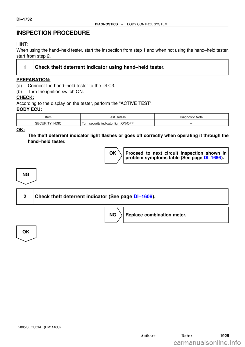
INSPECTION PROCEDURE
HINT:
When using the hand±held tester, start the inspection from step 1 and when not using the hand±held tester,
start from step 2.
1 Check theft deterrent indicator using hand±held tester.
PREPARATION:
(a) Connect the hand±held tester to the DLC3.
(b) Turn the ignition switch ON.
CHECK:
According to the display on the tester, perform the ºACTIVE TESTº.
BODY ECU:
ItemTest DetailsDiagnostic Note
SECURITY INDICTurn security indicator light ON/OFF±
OK:
The theft deterrent indicator light flashes or goes off correctly when operating it through the
hand±held tester.
OK Proceed to next circuit inspection shown in
problem symptoms table (See page DI±1686).
NG
2 Check theft deterrent indicator (See page DI±1608).
NG Replace combination meter.
OK
Page 1935 of 4323
± DIAGNOSTICSBODY CONTROL SYSTEM
DI±1733
1927 Author�: Date�:
2005 SEQUOIA (RM1146U)
3 Check wire harness and connector between theft deterrent indicator (combina-
tion meter) and body ECU, theft deterrent indicator (
combination meter) and body
ground (See page IN±35).
NG Repair or replace wire harness or connector.
OK
Proceed to next circuit inspection shown in
problem symptoms table
(See page DI±1686).
Page 1937 of 4323
± DIAGNOSTICSBODY CONTROL SYSTEM
DI±1735
1929 Author�: Date�:
2005 SEQUOIA (RM1146U)
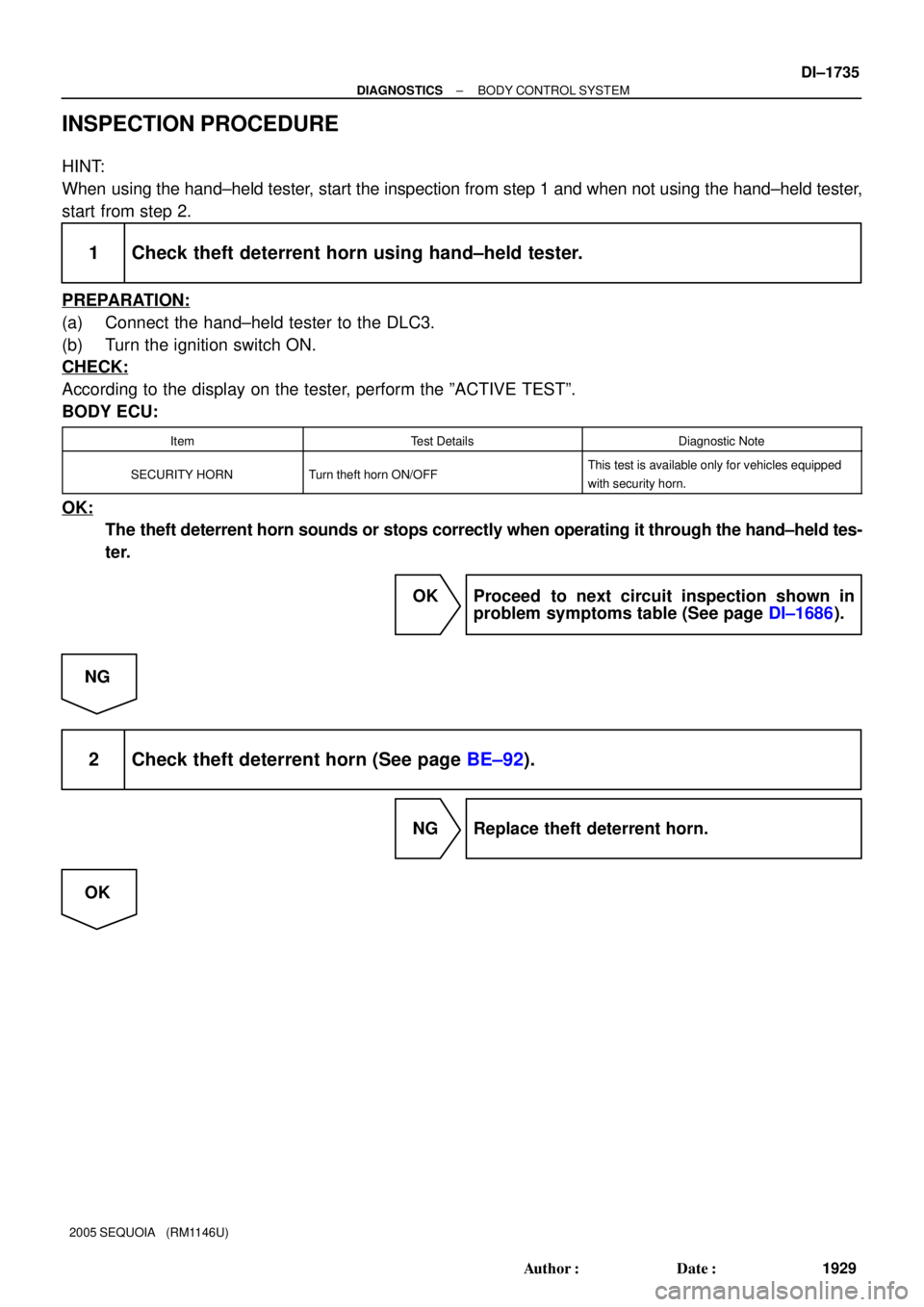
INSPECTION PROCEDURE
HINT:
When using the hand±held tester, start the inspection from step 1 and when not using the hand±held tester,
start from step 2.
1 Check theft deterrent horn using hand±held tester.
PREPARATION:
(a) Connect the hand±held tester to the DLC3.
(b) Turn the ignition switch ON.
CHECK:
According to the display on the tester, perform the ºACTIVE TESTº.
BODY ECU:
ItemTest DetailsDiagnostic Note
SECURITY HORNTurn theft horn ON/OFFThis test is available only for vehicles equipped
with security horn.
OK:
The theft deterrent horn sounds or stops correctly when operating it through the hand±held tes-
ter.
OK Proceed to next circuit inspection shown in
problem symptoms table (See page DI±1686).
NG
2 Check theft deterrent horn (See page BE±92).
NG Replace theft deterrent horn.
OK
Page 1938 of 4323
DI±1736
± DIAGNOSTICSBODY CONTROL SYSTEM
1930 Author�: Date�:
2005 SEQUOIA (RM1146U)
3 Check wire harness and connector between theft deterrent horn and body ECU,
theft deterrent horn and body ground (See page IN±35).
NG Repair or replace wire harness or connector.
OK
Proceed to next circuit inspection shown in
problem symptoms table
(See page DI±1686).