Page 1967 of 4323
± DIAGNOSTICSBODY CONTROL SYSTEM
DI±1765
1959 Author�: Date�:
2005 SEQUOIA (RM1146U)
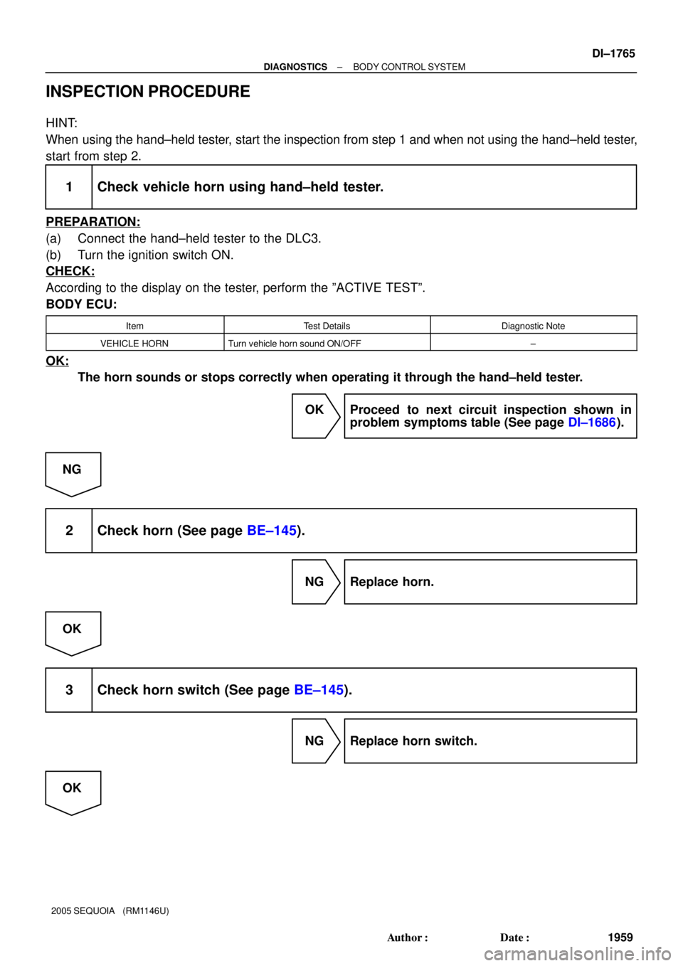
INSPECTION PROCEDURE
HINT:
When using the hand±held tester, start the inspection from step 1 and when not using the hand±held tester,
start from step 2.
1 Check vehicle horn using hand±held tester.
PREPARATION:
(a) Connect the hand±held tester to the DLC3.
(b) Turn the ignition switch ON.
CHECK:
According to the display on the tester, perform the ºACTIVE TESTº.
BODY ECU:
ItemTest DetailsDiagnostic Note
VEHICLE HORNTurn vehicle horn sound ON/OFF±
OK:
The horn sounds or stops correctly when operating it through the hand±held tester.
OK Proceed to next circuit inspection shown in
problem symptoms table (See page DI±1686).
NG
2 Check horn (See page BE±145).
NG Replace horn.
OK
3 Check horn switch (See page BE±145).
NG Replace horn switch.
OK
Page 1968 of 4323
DI±1766
± DIAGNOSTICSBODY CONTROL SYSTEM
1960 Author�: Date�:
2005 SEQUOIA (RM1146U)
4 Check horn relay (See page BE±145).
NG Replace horn relay.
OK
5 Check wire harness and connector between horn and body ECU, body ECU and
horn switch (See page IN±35).
NG Repair or replace wire harness or connector.
OK
Proceed to next circuit inspection shown in
problem symptoms table
(See page DI±1686).
Page 1971 of 4323

INSPECTION PROCEDURE
HINT:
When using the hand±held tester, start the inspection from step 1 and when not usin")
± DIAGNOSTICSBODY CONTROL SYSTEM
DI±1769
1963 Author�: Date�:
2005 SEQUOIA (RM1146U)
INSPECTION PROCEDURE
HINT:
When using the hand±held tester, start the inspection from step 1 and when not using the hand±held tester,
start from step 2.
1 Check remote mirror control switch using hand±held tester.
PREPARATION:
(a) Connect the hand±held tester to the DLC3.
(b) Turn the ignition switch ON.
CHECK:
According to the display on the tester, read the ºDATA LISTº.
BODY ECU:
ItemMeasurement Item/Display
(Range)Normal ConditionDiagnostic Note
MIRR SEL SW RRemote control mirror switch pas-
senger side/ON or OFF
ON: Remote control mirror switch
passenger side is selected
OFF: Remote control mirror switch
passenger side is not selected
±
MIRR SEL SW LRemote control mirror switch driv-
er side/ON or OFF
ON: Remote control mirror switch
driver side is selected
OFF: Remote control mirror switch
driver side is not selected
±
MIRR POS SW RRemote control mirror switch R
position/ON or OFF
ON: Remote control mirror switch
R position is selected
OFF: Remote control mirror switch
R position is not selected
±
MIRR POS SW LRemote control mirror switch L
position/ON or OFF
ON: Remote control mirror switch
L position is selected
OFF: Remote control mirror switch
L position is not selected
±
MIRR POS SW UPRemote control mirror switch UP
position/ON or OFF
ON: Remote control mirror switch
UP position is selected
OFF: Remote control mirror switch
UP position is not selected
±
MIRR POS SW DWNRemote control mirror switch
DOWN position/ON or OFF
ON: Remote control mirror switch
DOWN position is selected
OFF: Remote control mirror switch
DOWN position is not selected
±
OK:
The indication on the tester switches between ON and OFF in accordance with the remote con-
trol mirror switch status.
OK Proceed to next circuit inspection shown in
problem symptoms table (See page DI±1686).
NG
Page 1972 of 4323
DI±1770
± DIAGNOSTICSBODY CONTROL SYSTEM
1964 Author�: Date�:
2005 SEQUOIA (RM1146U)
2 Check remote control mirror switch (See page BE±115).
NG Replace remote control mirror switch.
OK
3 Check voltage between remote control mirror switch and battery, remote control
mirror switch and body ground.
PREPARATION:
(a) Disconnect the remote control mirror switch connector.
(b) Turn the ignition switch ON.
CHECK:
Measure the voltage between terminals R5±6 (B) and R5±2 (E) of the remote control mirror switch.
OK:
Voltage: 10 to 14 V
NG Repair or replace harness or connector.
OK
4 Check wire harness and connector between remote control mirror switch and re-
mote control mirror (See page IN±35).
NG Repair or replace harness or connector.
OK
5 Check retract motor operation (See page BE±115).
NG Replace remote control mirror.
OK
Page 1973 of 4323
± DIAGNOSTICSBODY CONTROL SYSTEM
DI±1771
1965 Author�: Date�:
2005 SEQUOIA (RM1146U)
6 Check wire harness and connector between remote control mirror switch and re-
mote control mirror (See page IN±35).
NG Repair or replace harness or connector.
OK
Proceed to next circuit inspection shown in
problem symptoms table
(See page DI±1686).
Page 1975 of 4323
± DIAGNOSTICSBODY CONTROL SYSTEM
DI±1773
1967 Author�: Date�:
2005 SEQUOIA (RM1146U)
INSPECTION PROCEDURE
1 Check driving position memory switch (See page DI±1518).
NG Replace driving position memory switch.
OK
2 Check wire harness and connector between driving position memory switch and
body ECU, driving position memory switch and body ground
(See page IN±35).
NG Repair or replace harness or connector.
OK
Proceed to next circuit inspection shown in
problem symptoms table
(See page DI±1686).
Page 1978 of 4323
DI±1776
± DIAGNOSTICSBODY CONTROL SYSTEM
1970 Author�: Date�:
2005 SEQUOIA (RM1146U)
INSPECTION PROCEDURE
1 Check voltage between terminals GBIG, GB+B and GND of glass breakage sen-
sor ECU.
PREPARATION:
Disconnect the glass breakage sensor ECU connector.
CHECK:
Measure the voltage between terminals GB+B and GND of the glass breakage sensor ECU.
OK:
Voltage: 10 to 14 V
PREPARATION:
Turn the ignition switch ON.
CHECK:
Measure the voltage between terminals GBIG and GND of the glass breakage sensor ECU.
OK:
Voltage: 10 to 14 V
NG Repair or replace wire harness or connector.
OK
2 Check wire harness and connector between glass breakage sensor ECU and
body ECU (See page IN±35).
NG Repair or replace harness or connector.
OK
3 Check wire harness and connector between glass breakage sensor ECU and
glass breakage sensor microphone (See page IN±35).
NG Repair or replace harness or connector.
OK
Page 1979 of 4323
I28726
G4
I28727
± DIAGNOSTICSBODY CONTROL SYSTEM
DI±1777
1971 Author�: Date�:
2005 SEQUOIA (RM1146U)
4 Check glass breakage sensor ECU (microphone output).
PREPARATION:
(a) Reconnect the glass breakage sensor ECU, glass break-
age sensor microphone and body ECU connectors.
(b) Connect an oscilloscope to terminal G4±3 of the glass
breakage sensor ECU and body ground.
(c) Turn the ignition switch ON.
CHECK:
Check the signal waveform according to the condition(s) in the
table below.
ItemCondition
Tool setting12 V/DIV, 300 ms/DIV
Vehicle condition
Tap the glass breakage sensor micro-
phone with a hard object such as your
fingernail.
OK:
As shown in the illustration.
NG Replace glass breakage sensor microphone.
HINT:
If the problem recurs even after replacement, replace the glass
breakage sensor ECU.
OK
Proceed to next circuit inspection shown in
problem symptoms table
(See page DI±1686).