Page 1951 of 4323
± DIAGNOSTICSBODY CONTROL SYSTEM
DI±1749
1943 Author�: Date�:
2005 SEQUOIA (RM1146U)
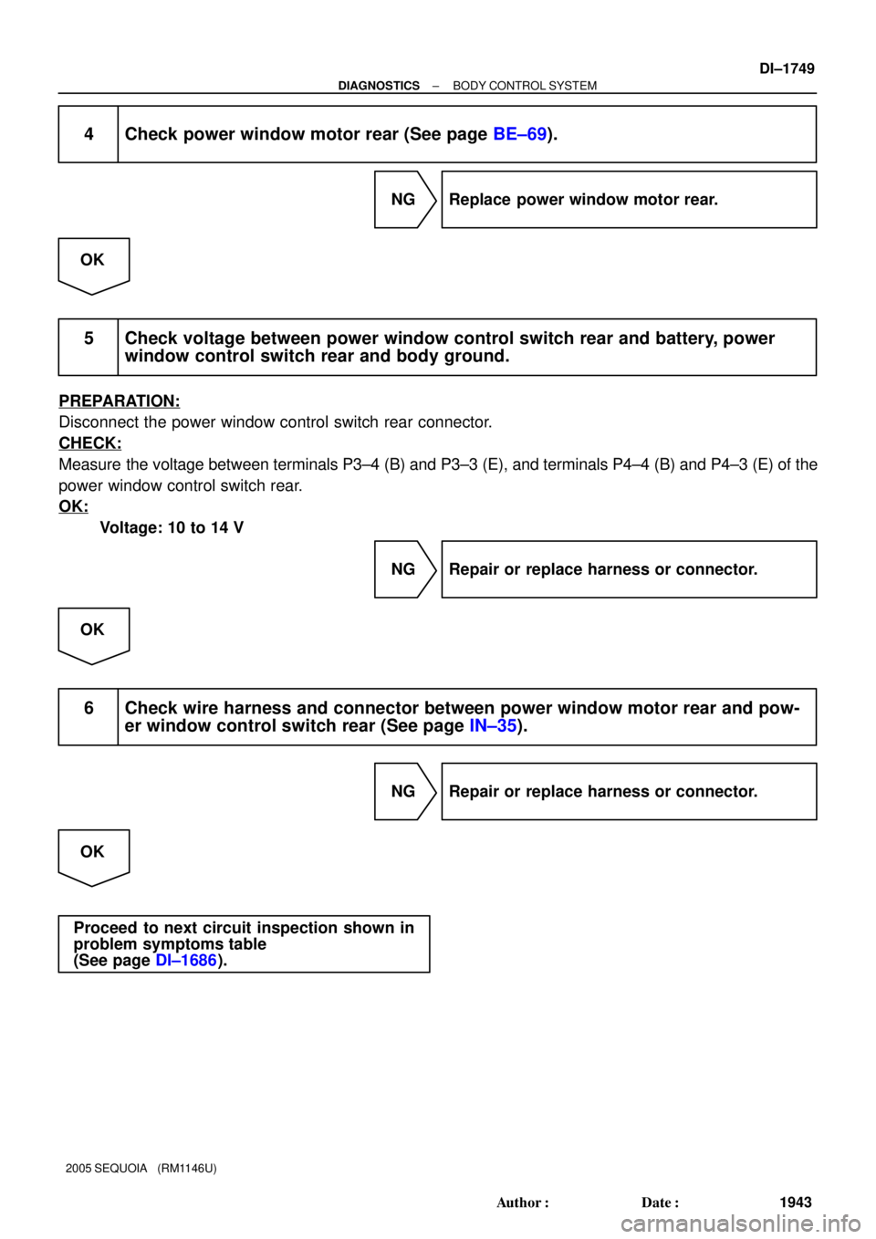
4 Check power window motor rear (See page BE±69).
NG Replace power window motor rear.
OK
5 Check voltage between power window control switch rear and battery, power
window control switch rear and body ground.
PREPARATION:
Disconnect the power window control switch rear connector.
CHECK:
Measure the voltage between terminals P3±4 (B) and P3±3 (E), and terminals P4±4 (B) and P4±3 (E) of the
power window control switch rear.
OK:
Voltage: 10 to 14 V
NG Repair or replace harness or connector.
OK
6 Check wire harness and connector between power window motor rear and pow-
er window control switch rear (See page IN±35).
NG Repair or replace harness or connector.
OK
Proceed to next circuit inspection shown in
problem symptoms table
(See page DI±1686).
Page 1953 of 4323

INSPECTION PROCEDURE
HINT:
When using the hand±held tester, start the inspection from step 1 and when not usin")
± DIAGNOSTICSBODY CONTROL SYSTEM
DI±1751
1945 Author�: Date�:
2005 SEQUOIA (RM1146U)
INSPECTION PROCEDURE
HINT:
When using the hand±held tester, start the inspection from step 1 and when not using the hand±held tester,
start from step 2.
1 Check headlight control switch using hand±held tester.
PREPARATION:
(a) Connect the hand±held tester to the DLC3.
(b) Turn the ignition switch ON.
CHECK:
According to the display on the tester, read the ºDATA LISTº.
BODY ECU:
ItemMeasurement Item/Display
(Range)Normal ConditionDiagnostic Note
AUTO LIGHT SWLight control switch (AUTO)/ON or
OFF
ON: Light control switch position is
AUTO
OFF: Light control switch position
is not AUTO
±
HEAD LIGHT SWLight control switch (HEAD)/ON or
OFF
ON: Light control switch position is
HEAD
OFF: Light control switch position
is not HEAD
±
TAIL LIGHT SWLight control switch (TAIL)/ON or
OFF
ON: Light control switch position is
TAIL
OFF: Light control switch position
is not TAIL
±
OK:
The indication on the tester switches between ON and OFF in accordance with the light control
switch status.
OK Proceed to next circuit inspection shown in
problem symptoms table (See page DI±1686).
NG
2 Check light control switch (See page BE±27).
NG Replace light control switch.
OK
Page 1954 of 4323
DI±1752
± DIAGNOSTICSBODY CONTROL SYSTEM
1946 Author�: Date�:
2005 SEQUOIA (RM1146U)
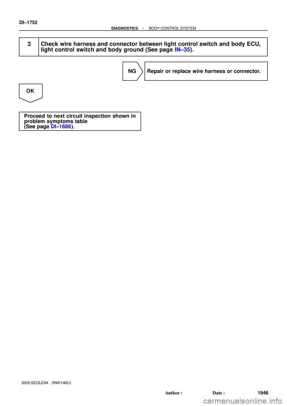
3 Check wire harness and connector between light control switch and body ECU,
light control switch and body ground (See page IN±35).
NG Repair or replace wire harness or connector.
OK
Proceed to next circuit inspection shown in
problem symptoms table
(See page DI±1686).
Page 1956 of 4323

INSPECTION PROCEDURE
1 Check automatic light control sensor.
When using hand±held tester:
PREPARATION:
(a) Con")
DI±1754
± DIAGNOSTICSBODY CONTROL SYSTEM
1948 Author�: Date�:
2005 SEQUOIA (RM1146U)
INSPECTION PROCEDURE
1 Check automatic light control sensor.
When using hand±held tester:
PREPARATION:
(a) Connect the hand±held tester to the DLC3.
(b) Turn the ignition switch and hand±held tester main switch ON.
BODY ECU:
ItemMeasurement Item/Display
(Range)Normal ConditionDiagnostic Note
ILLUMINATE RATEIllumination rate information/
MIN: 0 MAX: 99.99Condition value will be displayed
Normal value: 0.8 ms to 22.0 ms±
CHECK:
The illumination rate value should change within the following range such as when the light sensor is ex-
posed to light or covered by hand.
OK:
0.8 ms to 22.0 ms
HINT:
Time needed for the light sensor to generate one cycle of frequency according to the brightness.
When not using hand±held tester (See page BE±27):
NG Replace automatic light control sensor.
OK
2 Check harness and connector between automatic light control sensor and body
ECU (See page IN±35).
NG Repair or replace wire harness or connector.
OK
Proceed to next inspection shown in problem
symptoms table (See page DI±1686).
Page 1959 of 4323
± DIAGNOSTICSBODY CONTROL SYSTEM
DI±1757
1951 Author�: Date�:
2005 SEQUOIA (RM1146U)
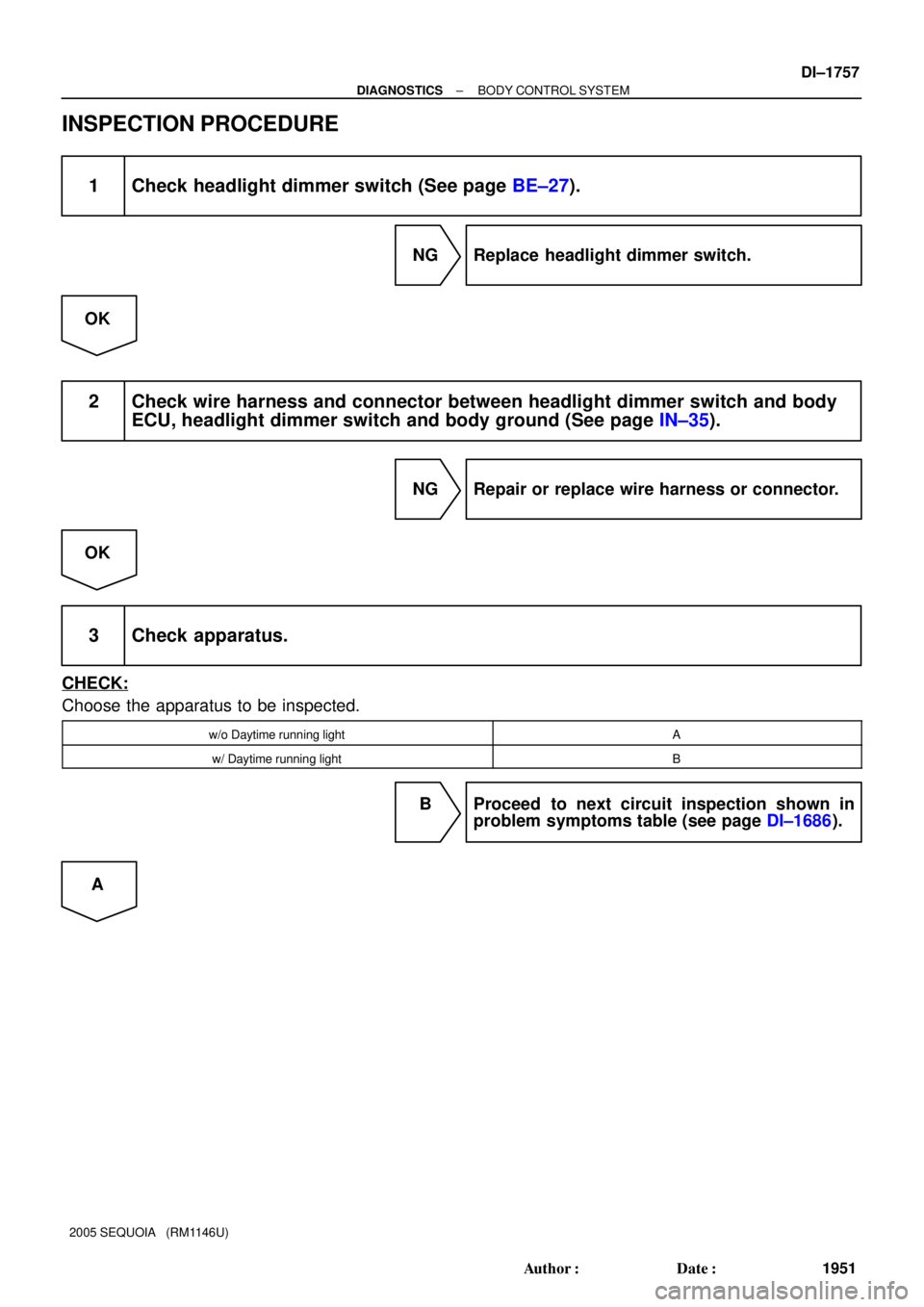
INSPECTION PROCEDURE
1 Check headlight dimmer switch (See page BE±27).
NG Replace headlight dimmer switch.
OK
2 Check wire harness and connector between headlight dimmer switch and body
ECU, headlight dimmer switch and body ground (See page IN±35).
NG Repair or replace wire harness or connector.
OK
3 Check apparatus.
CHECK:
Choose the apparatus to be inspected.
w/o Daytime running lightA
w/ Daytime running lightB
B Proceed to next circuit inspection shown in
problem symptoms table (see page DI±1686).
A
Page 1960 of 4323
DI±1758
± DIAGNOSTICSBODY CONTROL SYSTEM
1952 Author�: Date�:
2005 SEQUOIA (RM1146U)
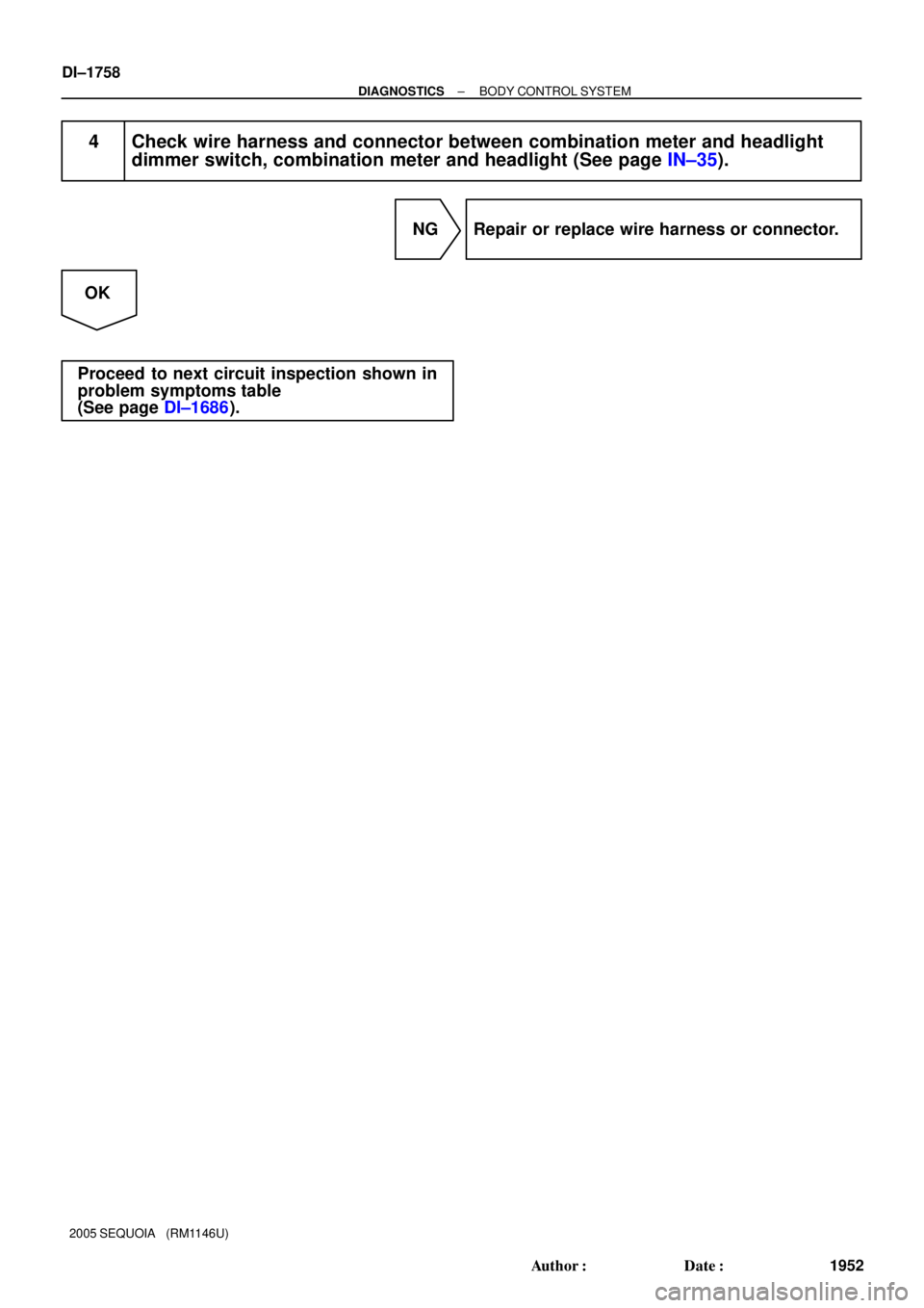
4 Check wire harness and connector between combination meter and headlight
dimmer switch, combination meter and headlight (See page IN±35).
NG Repair or replace wire harness or connector.
OK
Proceed to next circuit inspection shown in
problem symptoms table
(See page DI±1686).
Page 1964 of 4323
DI±1762
± DIAGNOSTICSBODY CONTROL SYSTEM
1956 Author�: Date�:
2005 SEQUOIA (RM1146U)
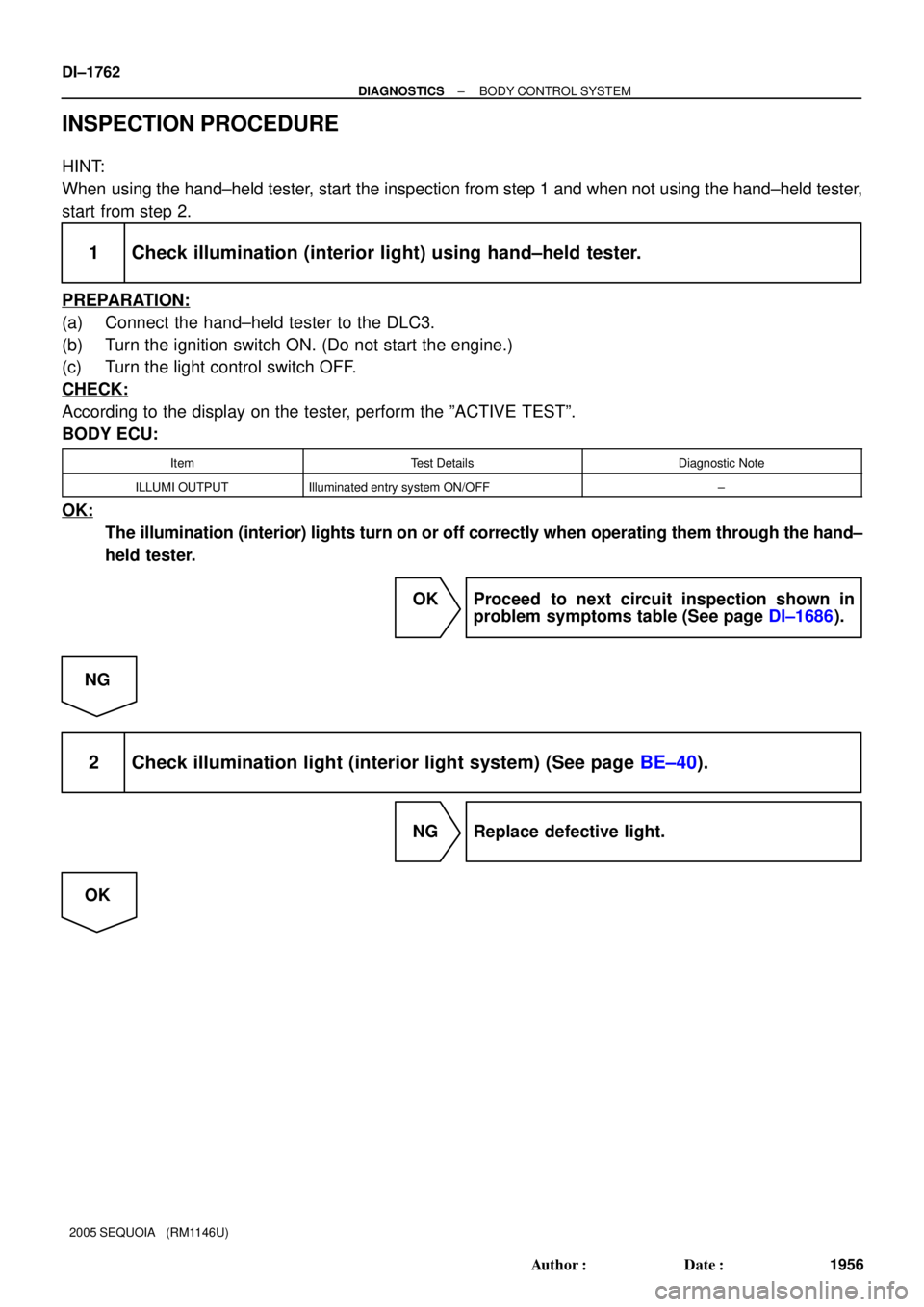
INSPECTION PROCEDURE
HINT:
When using the hand±held tester, start the inspection from step 1 and when not using the hand±held tester,
start from step 2.
1 Check illumination (interior light) using hand±held tester.
PREPARATION:
(a) Connect the hand±held tester to the DLC3.
(b) Turn the ignition switch ON. (Do not start the engine.)
(c) Turn the light control switch OFF.
CHECK:
According to the display on the tester, perform the ºACTIVE TESTº.
BODY ECU:
ItemTest DetailsDiagnostic Note
ILLUMI OUTPUTIlluminated entry system ON/OFF±
OK:
The illumination (interior) lights turn on or off correctly when operating them through the hand±
held tester.
OK Proceed to next circuit inspection shown in
problem symptoms table (See page DI±1686).
NG
2 Check illumination light (interior light system) (See page BE±40).
NG Replace defective light.
OK
Page 1965 of 4323
± DIAGNOSTICSBODY CONTROL SYSTEM
DI±1763
1957 Author�: Date�:
2005 SEQUOIA (RM1146U)
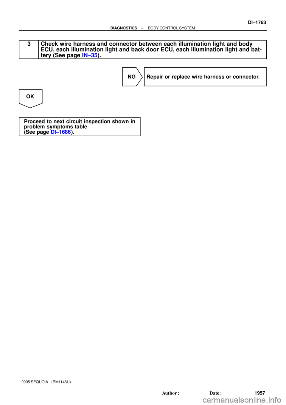
3 Check wire harness and connector between each illumination light and body
ECU, each illumination light and back door ECU, each illumination light and bat-
tery (See page IN±35).
NG Repair or replace wire harness or connector.
OK
Proceed to next circuit inspection shown in
problem symptoms table
(See page DI±1686).