Page 2048 of 4323
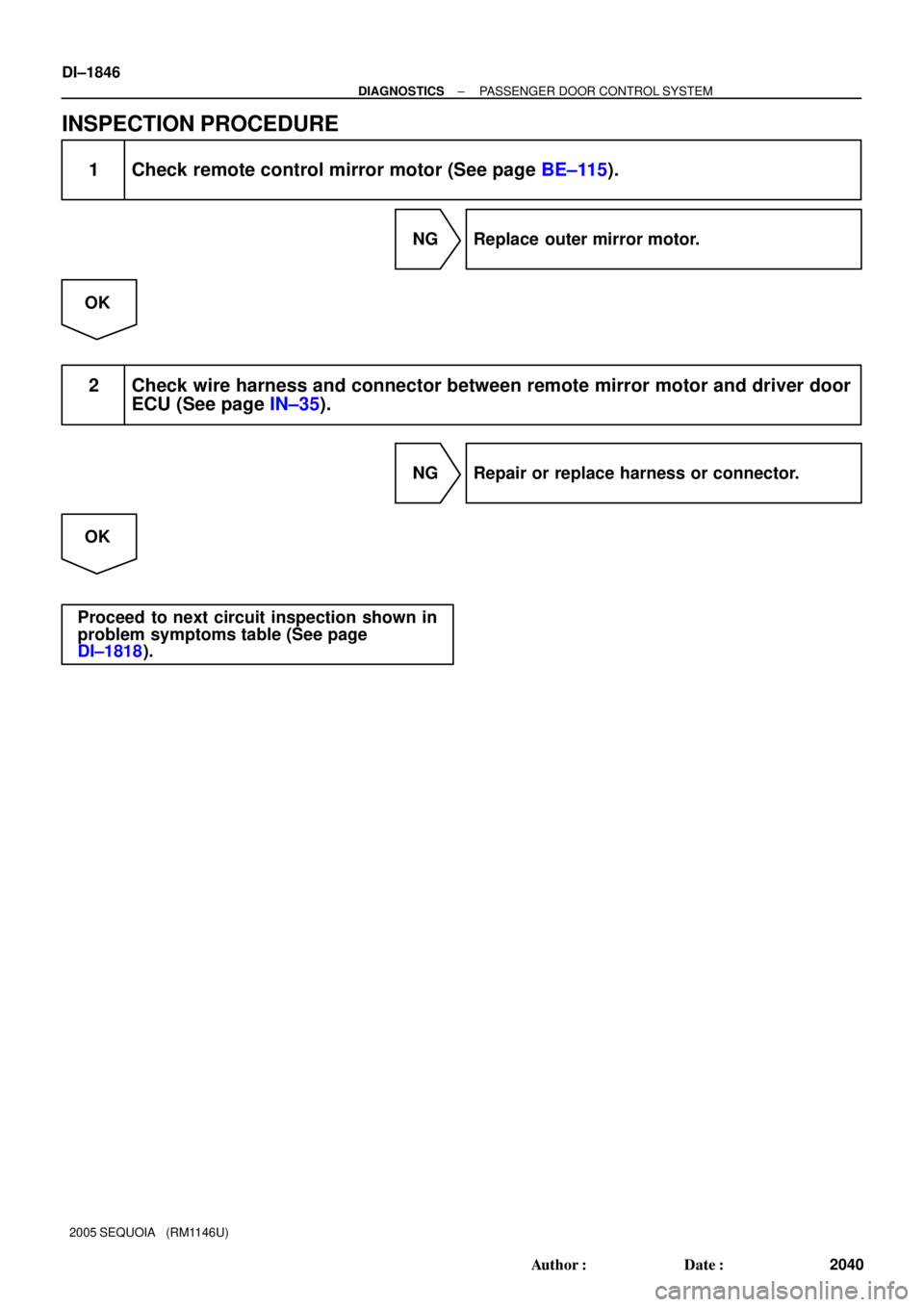
DI±1846
± DIAGNOSTICSPASSENGER DOOR CONTROL SYSTEM
2040 Author�: Date�:
2005 SEQUOIA (RM1146U)
INSPECTION PROCEDURE
1 Check remote control mirror motor (See page BE±115).
NG Replace outer mirror motor.
OK
2 Check wire harness and connector between remote mirror motor and driver door
ECU (See page IN±35).
NG Repair or replace harness or connector.
OK
Proceed to next circuit inspection shown in
problem symptoms table (See page
DI±1818).
Page 2050 of 4323
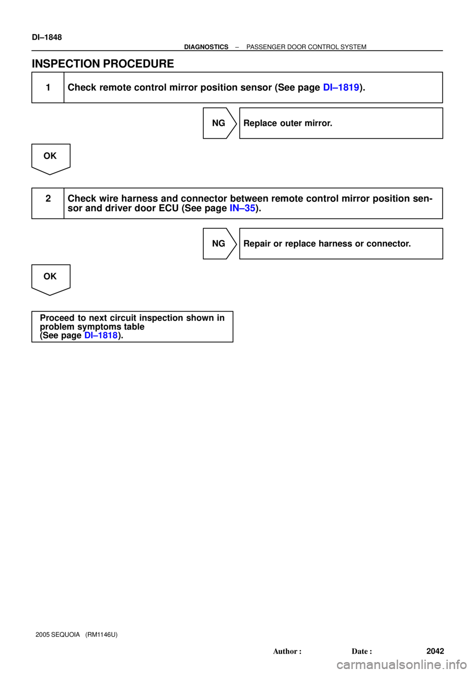
DI±1848
± DIAGNOSTICSPASSENGER DOOR CONTROL SYSTEM
2042 Author�: Date�:
2005 SEQUOIA (RM1146U)
INSPECTION PROCEDURE
1 Check remote control mirror position sensor (See page DI±1819).
NG Replace outer mirror.
OK
2 Check wire harness and connector between remote control mirror position sen-
sor and driver door ECU (See page IN±35).
NG Repair or replace harness or connector.
OK
Proceed to next circuit inspection shown in
problem symptoms table
(See page DI±1818).
Page 2051 of 4323
± DIAGNOSTICSPASSENGER DOOR CONTROL SYSTEM
DI±1849
2043 Author�: Date�:
2005 SEQUOIA (RM1146U)
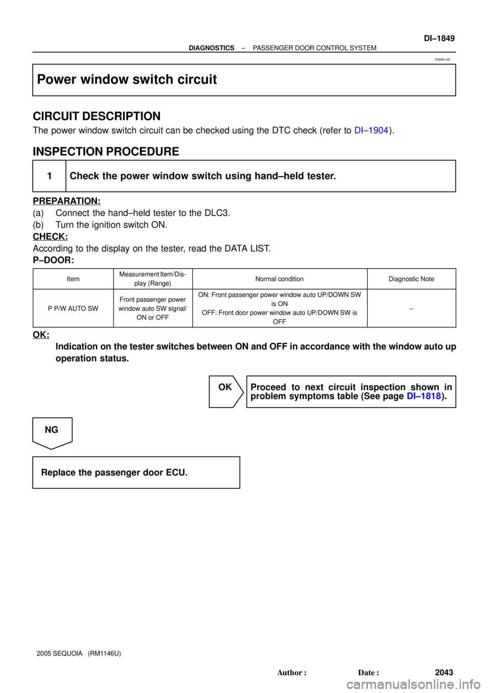
Power window switch circuit
CIRCUIT DESCRIPTION
The power window switch circuit can be checked using the DTC check (refer to DI±1904).
INSPECTION PROCEDURE
1 Check the power window switch using hand±held tester.
PREPARATION:
(a) Connect the hand±held tester to the DLC3.
(b) Turn the ignition switch ON.
CHECK:
According to the display on the tester, read the DATA LIST.
P±DOOR:
ItemMeasurement Item/Dis-
play (Range)Normal conditionDiagnostic Note
P P/W AUTO SW
Front passenger power
window auto SW signal/
ON or OFFON: Front passenger power window auto UP/DOWN SW
is ON
OFF: Front door power window auto UP/DOWN SW is
OFF
±
OK:
Indication on the tester switches between ON and OFF in accordance with the window auto up
operation status.
OK Proceed to next circuit inspection shown in
problem symptoms table (See page DI±1818).
NG
Replace the passenger door ECU.
DI94M±05
Page 2052 of 4323
DID9F±01
DI±1850
± DIAGNOSTICSBACK DOOR CONTROL SYSTEM
2044 Author�: Date�:
2005 SEQUOIA (RM1146U)
BACK DOOR CONTROL SYSTEM
PRECAUTION
NOTICE:
When disconnecting the battery terminal, initialize the following system after the terminal is recon-
nected.
System NameSee Page
Back Door Power Window Control SystemBE±77
Page 2054 of 4323
DI57D±06
Customer Problem Analysis
Vehicle Brought to Workshop
Problem Symptom ConfirmationSymptom Simulation Symptom does not
occur
Circuit Inspection
Identification of Problem
Repair or replace
Confirmation Test
EndTitles inside
are titles of pages in this
manual, with the page number indicated in
the bottom portion. See the indicated pages
for detailed explanations.
1
23
5
8P. IN±24 P. DI±1853
P. DI±1861 ± DI±1885
Symptom
occurs
Step 4, 6, 8: Diagnostic steps permitting use of the hand±held tester. 7
Problem Symptoms Table
P. DI±1854
P. DI±1904
Multiplex communication system inspection * 4*: Confirm that there is no trouble by
DTC check.
6 DI±1852
± DIAGNOSTICSBACK DOOR CONTROL SYSTEM
2046 Author�: Date�:
2005 SEQUOIA (RM1146U)
HOW TO PROCEED WITH TROUBLESHOOTING
HINT:
This ECU is connected to the multiplex communication system. Therefore, be sure to check that there is no
trouble in the multiplex communication system before performing the troubleshooting.
Page 2056 of 4323

PROBLEM SYMPTOMS TABLE
REAR WIPER AND WASHER
SymptomSuspected AreaSee page
Rear wiper does not o")
DI57H±07
DI±1854
± DIAGNOSTICSBACK DOOR CONTROL SYSTEM
2048 Author�: Date�:
2005 SEQUOIA (RM1146U)
PROBLEM SYMPTOMS TABLE
REAR WIPER AND WASHER
SymptomSuspected AreaSee page
Rear wiper does not operate.
1. Wiper switch circuit
2. Rear wiper motor circuit
3. Rear wiper limit switch circuit
4. Back door power window pulse sensor circuit
5. Body ECU
6. Back door ECUDI±1704
DI±1880
DI±1885
DI±1877
IN±35
IN±35
Rear washer does not operate.1. Washer switch and washer motor circuit
2. Body ECUDI±1704
IN±35
Wiper does not operate when washer switch is ON.1. Wiper switch and washer motor circuit
2. Body ECUDI±1704
IN±35
OTHERS
SymptomSuspected AreaSee page
Back door power window does not operate.
1. Back door power window switch circuit
2. Back door power window pulse sensor circuit
3. Back door power window motor circuit
4. Body ECU
5. Back door ECUDI±1718
DI±1877
DI±1874
IN±35
IN±35
Back door lock does not operate.
1. Back door key lock and unlock switch circuit
2. Back door lock motor circuit
3. Back door unlock detection switch circuit
4. Back door courtesy light switch circuit
5. Back door key lock and unlock switch circuit
6. Back door ECUDI±1882
DI±1872
DI±1869
DI±1864
DI±1882
IN±35
Luggage room light does not come on.
1. Luggage room light circuit
2. Back door courtesy light switch circuit
3. Body door ECUDI±1867
DI±1864
IN±35
Whole functions of the back door control system do not operate.1. Power source circuit
2. Back door ECUDI±1861
IN±35
Page 2064 of 4323
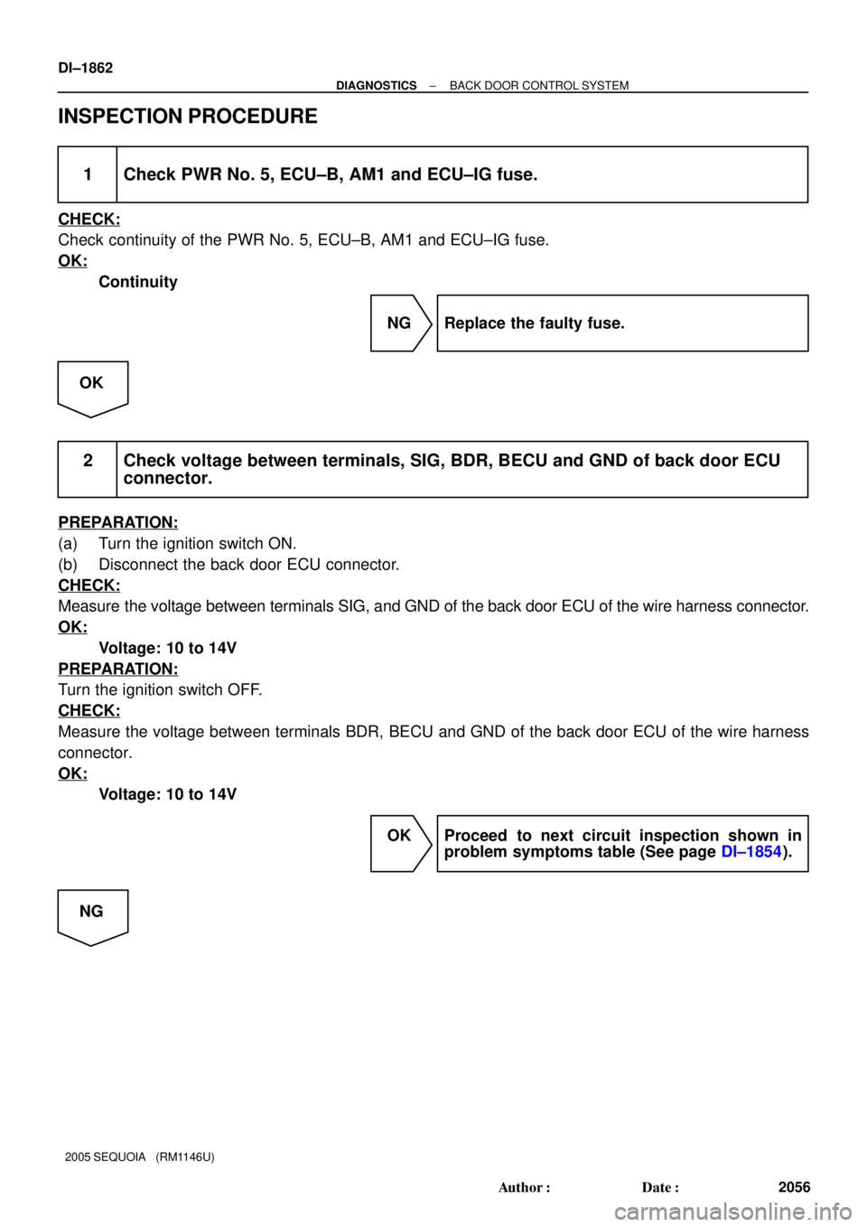
DI±1862
± DIAGNOSTICSBACK DOOR CONTROL SYSTEM
2056 Author�: Date�:
2005 SEQUOIA (RM1146U)
INSPECTION PROCEDURE
1 Check PWR No. 5, ECU±B, AM1 and ECU±IG fuse.
CHECK:
Check continuity of the PWR No. 5, ECU±B, AM1 and ECU±IG fuse.
OK:
Continuity
NG Replace the faulty fuse.
OK
2 Check voltage between terminals, SIG, BDR, BECU and GND of back door ECU
connector.
PREPARATION:
(a) Turn the ignition switch ON.
(b) Disconnect the back door ECU connector.
CHECK:
Measure the voltage between terminals SIG, and GND of the back door ECU of the wire harness connector.
OK:
Voltage: 10 to 14V
PREPARATION:
Turn the ignition switch OFF.
CHECK:
Measure the voltage between terminals BDR, BECU and GND of the back door ECU of the wire harness
connector.
OK:
Voltage: 10 to 14V
OK Proceed to next circuit inspection shown in
problem symptoms table (See page DI±1854).
NG
Page 2065 of 4323
± DIAGNOSTICSBACK DOOR CONTROL SYSTEM
DI±1863
2057 Author�: Date�:
2005 SEQUOIA (RM1146U)
3 Check wire harness and connector between back door ECU and battery
(See page IN±35).
NG Repair or replace wire harness or connector.
OK
4 Check wire harness and connector between back door ECU and body ground
(See page IN±35).
NG Repair or replace wire harness or connector.
OK
Proceed to next circuit inspection shown in
problem symptoms table
(See page DI±1854).