Page 1760 of 1897
B01161
P13528
- STARTINGSTARTER
ST-7
1260 Author�: Date�:
2001 AVALON (RM808U)
5. REMOVE BRUSH HOLDER
(a) Remove the 2 screws and end cover from the field frame.
Torque: 1.5 N´m (15 kgf´cm, 13 in.´lbf)
(b) Remove the O-ring from the field frame.
(c) Using a screwdriver, hold the spring back and disconnect
the brush from the brush holder.
Disconnect the 4 brushes, and remove the brush holder.
NOTICE:
Check that the positive (+) lead wires are not grounded.
6. REMOVE ARMATURE FROM FIELD FRAME
Page 1766 of 1897
ST04O-02
- STARTINGSTARTER
ST-5
1258 Author�: Date�:
2001 AVALON (RM808U)
REMOVAL
1. REMOVE AIR CLEANER CAP
2. REMOVE BATTERY AND TRAY
3. REMOVE CRUISE CONTROL ACTUATOR
(a) Disconnect the actuator connector and clamp.
(b) Remove the 3 bolts, and disconnect the actuator with the bracket.
4. REMOVE STARTER
(a) Disconnect the starter connector.
(b) Remove the nut, and disconnect the starter cable.
(c) Remove the 2 bolts, throttle cable clamp and starter.
Torque: 39 N´m (400 kgf´cm, 29 ft´lbf)
Page 1772 of 1897
B01240
SST
B01241
ST-16
- STARTINGSTARTER
1269 Author�: Date�:
2001 AVALON (RM808U)
�If the contact plate is not pressed down with the spe-
cified pressure, the contact plate may tilt due to coil
deformation or the tightening of the nut.
(2) Using SST, tighten the nuts to the specified torque.
SST 09810-38140
Torque: 17 N´m (173 kgf´cm, 12 ft´lbf)
NOTICE:
If the nut is over tightened, it may cause cracks on the in-
side of the insulator.
(g) Clean the contact surfaces of the remaining contact plate
and plunger with a dry shop rag.
(h) Install the plunger, new gasket, end cover and 3 bolts.
Torque: 2.5 N´m (25 kgf´cm, 22 in.´lbf)
Page 1781 of 1897
SR0ET-05
F09931
Stabilizer Bar
Clamp PlateNo. 1 Fuel Tube Protector
Intermediate Shaft
Sub-assembly
Return Tube
Pressure Feed Tube
PS Gear Assembly
* For use with SSTCotter Pin � Non-reusable part
19 (190, 14)
19 (190, 14)
10 (100, 7)
35 (360, 26)
181 (1,850, 134)
181 (1,850, 134)
49 (500, 36)
49 (500, 36)N´m (kgf´cm, ft´lbf) : Specified torque
25 (250, 18)
*28 (290, 21)
Cotter Pin25 (250, 18)
*28 (290, 21)
O-Ring �
Power steering fluid�
�
- STEERINGPOWER STEERING GEAR
SR-37
1500 Author�: Date�:
2001 AVALON (RM808U)
POWER STEERING GEAR
COMPONENTS
Page 1782 of 1897
Z19562
� O-Ring
* For use with SST � Non-reusable partRack Housing
No. 2 Grommet
Rack HousingRack Boot
Clip
Tie Rod End
Lock Nut
Rack End
Steering Rack Rack Housing
No. 2 Bracket� Clamp
� Claw Washer
� Teflon Ring
� Oil Seal
� Wire
� Oil Seal
Molybdenum disulfide lithium base grease
Power steering fluidCylinder End Stopper
Bushing � Claw Washer Rack End
83 (850, 61)
*60 (610, 44)
� Clamp Rack Boot Clip
Lock Nut Tie Rod End
74 (750, 54)
74 (750, 54)
N´m (kgf´cm, ft´lbf) : Specified torque
� O-Ring
83 (850, 61)
*60 (610, 44)
SR-38
- STEERINGPOWER STEERING GEAR
1501 Author�: Date�:
2001 AVALON (RM808U)
Page 1783 of 1897
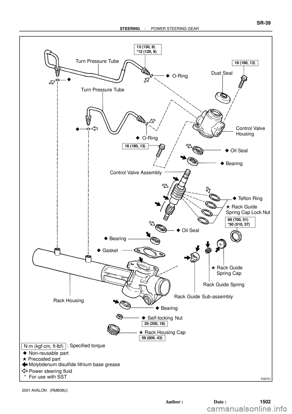
F09751
� Non-reusable part� Oil Seal � O-Ring
Molybdenum disulfide lithium base grease
Power steering fluid � Precoated part� O-Ring Turn Pressure Tube
Dust Seal
�
Control Valve AssemblyControl Valve
Housing Turn Pressure Tube
�
� Oil Seal
� Bearing
� Teflon Ring
� Bearing
� Gasket
Rack Guide Spring
Rack Guide Sub-assembly
Rack Housing
� Bearing� Rack Guide
Spring Cap Lock Nut
� Rack Guide
Spring Cap
� Self-locking Nut
� Rack Housing Cap
13 (130, 9)
*12 (120, 9)
18 (180, 13)
18 (180, 13)
69 (700, 51)
*50 (510, 37)
25 (250, 18)
59 (600, 43)
N´m (kgf´cm, ft´lbf): Specified torque
* For use with SST
- STEERINGPOWER STEERING GEAR
SR-39
1502 Author�: Date�:
2001 AVALON (RM808U)
Page 1789 of 1897

INSTALLATION
1. INSTALL PS GEAR ASSEMBLY
(a) Install the PS gear assembly from the LH")
SR0EY-06
F13589
SST
Fulcrum Length
SR-56
- STEERINGPOWER STEERING GEAR
1519 Author�: Date�:
2001 AVALON (RM808U)
INSTALLATION
1. INSTALL PS GEAR ASSEMBLY
(a) Install the PS gear assembly from the LH of the vehicle.
NOTICE:
Do not damage the turn pressure tubes.
(b) Install the 2 gear assembly set bolts and nuts.
Torque: 181 N´m (1,850 kgf´cm, 134 ft´lbf)
HINT:
Lift up the stabilizer bar and install the bolts.
2. INSTALL NO. 1 FUEL TUBE PROTECTOR
Install the No. 1 fuel tube protector with 2 bolts and nut.
3. CONNECT STABILIZER BAR
Connect the stabilizer bar with the 4 bolts.
Torque: 19 N´m (190 kgf´cm, 14 ft´lbf)
4. CONNECT PRESSURE FEED AND RETURN TUBES
(a) Coat 2 new O-rings with power steering fluid and install
them to the pressure feed and return tubes.
(b) Using SST, connect the pressure feed and return tubes.
SST 09023-38400
Torque: 28 N´m (290 kgf´cm, 21 ft´lbf)
HINT:
�Use a torque wrench with a fulcrum length of 300 mm
(11.81 in.).
�This torque value is effective in case that SST is parallel
to a torque wrench.
5. CONNECT CLAMP PLATE
Connect the clamp plate with nut.
Torque: 10 N´m (100 kgf´cm, 7 ft´lbf)
6. CONNECT INTERMEDIATE SHAFT SUB-ASSEMBLY
(See page SR-22)
7. CONNECT RH AND LH TIE ROD ENDS
(See page SA-13)
8. PLACE FRONT WHEELS FACING STRAIGHT AHEAD
HINT:
Do it with the front of the vehicle jacked up.
9. CENTER SPIRAL CABLE (See page SR-22)
10. INSTALL STEERING WHEEL
(a) Align the matchmarks on the steering wheel and steering
column main shaft.
(b) Temporarily tighten the steering wheel set nut.
(c) Connect the connector.
11. BLEED POWER STEERING SYSTEM
(See page SR-4)
Page 1790 of 1897
- STEERINGPOWER STEERING GEAR
SR-57
1520 Author�: Date�:
2001 AVALON (RM808U)
12. CHECK STEERING WHEEL CENTER POINT
13. TORQUE STEERING WHEEL SET NUT
Torque: 50 N´m (510 kgf´cm, 37 ft´lbf)
14. INSTALL STEERING WHEEL PAD (See page SR-22)
15. CHECK FRONT WHEEL ALIGNMENT
(See page SA-4)
16. w/ VSC:
PERFORM STEERING ANGLE SENSOR ZERO POINT
CALIBRATION (See page DI-252)