Page 404 of 1897

BO41D-01
H15909
H12121
2 Clips
Clip
- BODYLUGGAGE COMPARTMENT DOOR AND HINGE
BO-31
1816 Author�: Date�:
2001 AVALON (RM808U)
REMOVAL
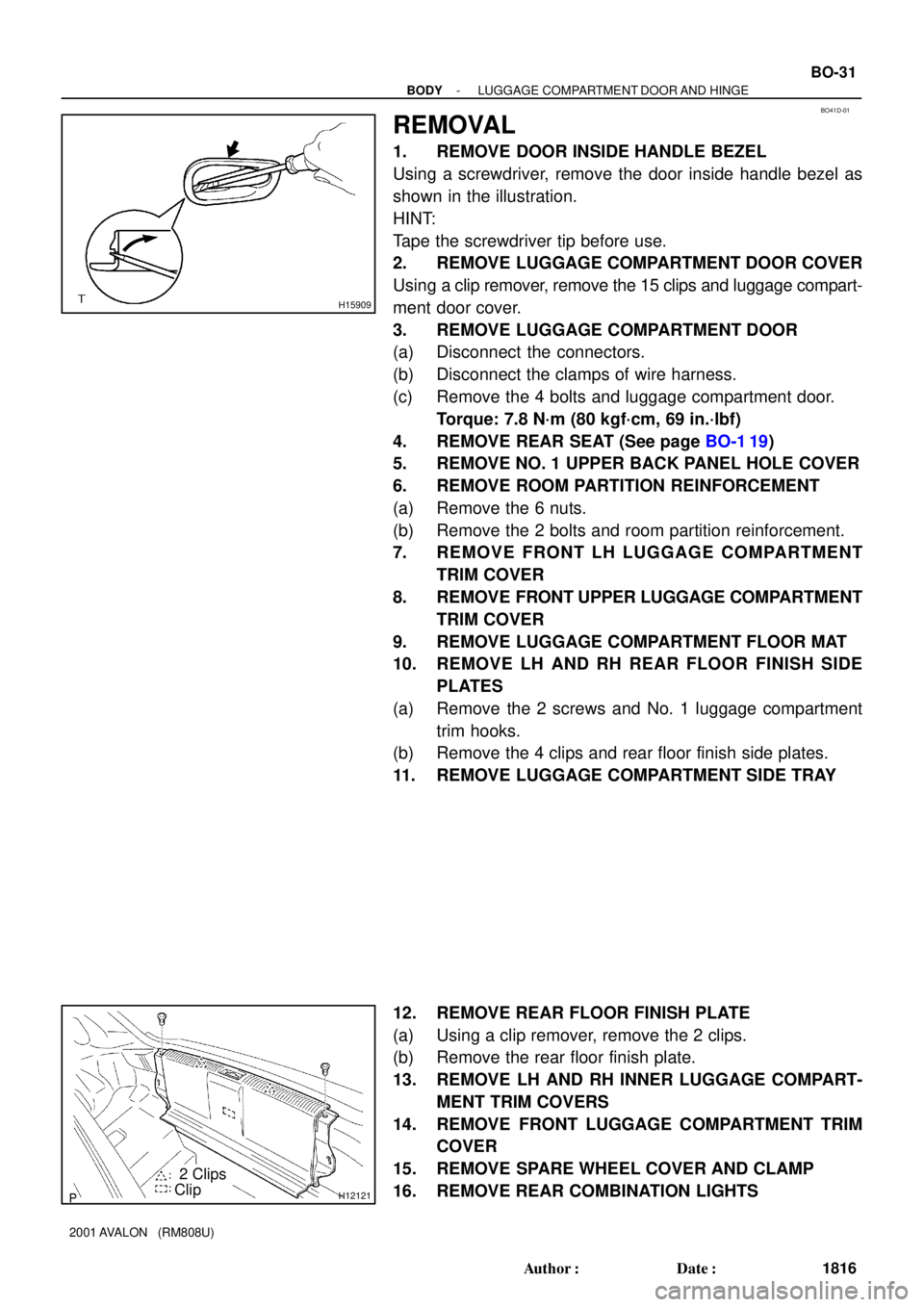
1. REMOVE DOOR INSIDE HANDLE BEZEL
Using a screwdriver, remove the door inside handle bezel as
shown in the illustration.
HINT:
Tape the screwdriver tip before use.
2. REMOVE LUGGAGE COMPARTMENT DOOR COVER
Using a clip remover, remove the 15 clips and luggage compart-
ment door cover.
3. REMOVE LUGGAGE COMPARTMENT DOOR
(a) Disconnect the connectors.
(b) Disconnect the clamps of wire harness.
(c) Remove the 4 bolts and luggage compartment door.
Torque: 7.8 N´m (80 kgf´cm, 69 in.´lbf)
4. REMOVE REAR SEAT (See page BO-1 19)
5. REMOVE NO. 1 UPPER BACK PANEL HOLE COVER
6. REMOVE ROOM PARTITION REINFORCEMENT
(a) Remove the 6 nuts.
(b) Remove the 2 bolts and room partition reinforcement.
7. REMOVE FRONT LH LUGGAGE COMPARTMENT
TRIM COVER
8. REMOVE FRONT UPPER LUGGAGE COMPARTMENT
TRIM COVER
9. REMOVE LUGGAGE COMPARTMENT FLOOR MAT
10. REMOVE LH AND RH REAR FLOOR FINISH SIDE
PLATES
(a) Remove the 2 screws and No. 1 luggage compartment
trim hooks.
(b) Remove the 4 clips and rear floor finish side plates.
11. REMOVE LUGGAGE COMPARTMENT SIDE TRAY
12. REMOVE REAR FLOOR FINISH PLATE
(a) Using a clip remover, remove the 2 clips.
(b) Remove the rear floor finish plate.
13. REMOVE LH AND RH INNER LUGGAGE COMPART-
MENT TRIM COVERS
14. REMOVE FRONT LUGGAGE COMPARTMENT TRIM
COVER
15. REMOVE SPARE WHEEL COVER AND CLAMP
16. REMOVE REAR COMBINATION LIGHTS
Page 527 of 1897
BR0LJ-03
BR0823
Contract
Expand BR-46
- BRAKEPARKING BRAKE
1445 Author�: Date�:
2001 AVALON (RM808U)
REASSEMBLY
Reassembly is in the reverse order of disassembly (See
page BR-44).
NOTICE:
Apply high temperature grease to the parts indicated by the
arrows (See page BR-43).
1. ADJUST PARKING BRAKE SHOE CLEARANCE
(a) Temporarily install the hub nuts.
(b) Remove the hole plug.
(c) Turn the adjuster and expand the shoes until the disc
locks.
(d) Return the adjuster 8 notches.
(e) Install the hole plug.
2. SETTLING PARKING BRAKE SHOES AND DISC
(a) Depress the parking brake pedal with 147 N (15 kgf, 33
lbf).
(b) Drive the vehicle at about 50 km/h (31 mph) on a safe, lev-
el and dry road.
(c) Drive the vehicle for about 400 meters (0.25 mile) in this
condition.
(d) Repeat this procedure 2 or 3 times.
3. RECHECK AND ADJUST PARKING BRAKE PEDAL
TRAVEL (See page BR-9)
Page 778 of 1897

AT4252
0 - 1 mm (0 - 0.04 in.)
Q00199
D02450P N
R
- DIAGNOSTICSAUTOMATIC TRANSAXLE
DI-167
323 Author�: Date�:
2001 AVALON (RM808U)
(d) Check the fluid leaks.
Check for leaks in the transaxle.
If there are leaks, it is necessary to repair or replace O-rings,
gasket, oil seals, plugs or other parts.
(e) Inspect and adjust the throttle cable.
(1) Check that the accelerator pedal is fully released.
(2) Check that the inner cable is not slack.
(3) Measure the distance between the outer cable end
and stopper on the cable.
Standard distance: 0 - 1 mm (0 - 0.04 in.)
If the distance is not the standard, adjust the cable by adjusting
nuts.
(f) Inspect and adjust the shift lever position.
When shifting the shift lever from the N position to other
positions, check that the lever can be shifted smoothly
and accurately to each position and that the position indi-
cator is aligned with the correct position.
If the indicator is not aligned with the correct position, carry out
the following adjustment procedures.
(1) Loosen the nut on the shift lever.
(2) Push the control shaft fully downward.
(3) Return the control shaft lever 2 notches to N posi-
tion.
(4) Set the shift lever to N position.
(5) While holding the shift lever lightly toward the R
position side, tighten the shift lever nut.
Torque: 13 N´m (130 kgf´cm, 9 ft´lbf)
(6) Start the engine and make sure that the vehicle
moves forward when shifting the lever from the N to
D position and reverses when shifting it to the R
position.
Page 1343 of 1897

A05194
L = 133 mm (5.24 in.)
L = 180 mm (7.09 in.)L = 72 mm (2.83 in.)
L = 335 mm (13.19 in.)L = 180 mm
(7.09 in.)
L = Length Join
LineJoin
Line
Z14262New Gasket
- ENGINE MECHANICALCYLINDER HEAD
EM-67
1051 Author�: Date�:
2001 AVALON (RM808U)
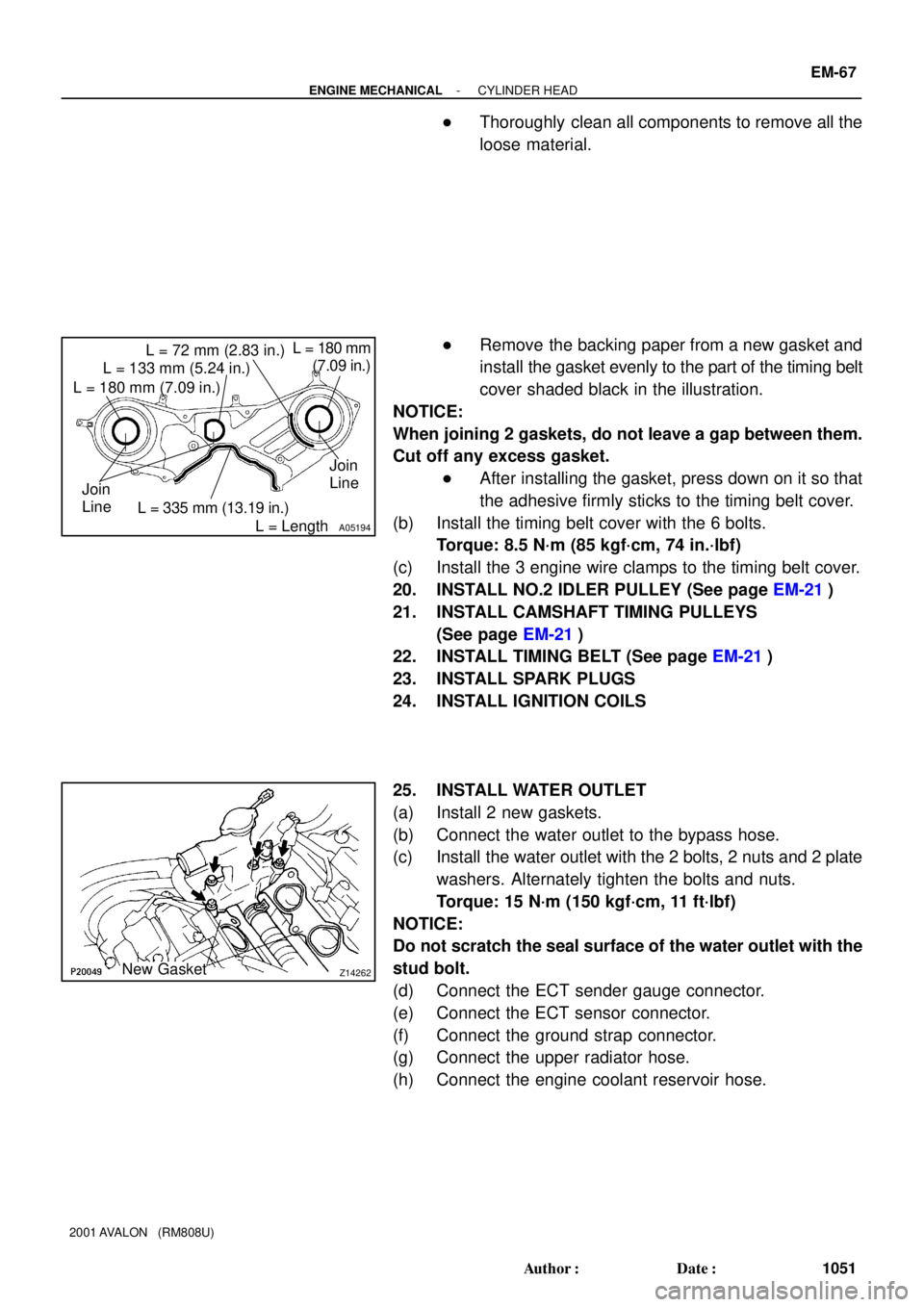
�Thoroughly clean all components to remove all the
loose material.
�Remove the backing paper from a new gasket and
install the gasket evenly to the part of the timing belt
cover shaded black in the illustration.
NOTICE:
When joining 2 gaskets, do not leave a gap between them.
Cut off any excess gasket.
�After installing the gasket, press down on it so that
the adhesive firmly sticks to the timing belt cover.
(b) Install the timing belt cover with the 6 bolts.
Torque: 8.5 N´m (85 kgf´cm, 74 in.´lbf)
(c) Install the 3 engine wire clamps to the timing belt cover.
20. INSTALL NO.2 IDLER PULLEY (See page EM-21)
21. INSTALL CAMSHAFT TIMING PULLEYS
(See page EM-21)
22. INSTALL TIMING BELT (See page EM-21)
23. INSTALL SPARK PLUGS
24. INSTALL IGNITION COILS
25. INSTALL WATER OUTLET
(a) Install 2 new gaskets.
(b) Connect the water outlet to the bypass hose.
(c) Install the water outlet with the 2 bolts, 2 nuts and 2 plate
washers. Alternately tighten the bolts and nuts.
Torque: 15 N´m (150 kgf´cm, 11 ft´lbf)
NOTICE:
Do not scratch the seal surface of the water outlet with the
stud bolt.
(d) Connect the ECT sender gauge connector.
(e) Connect the ECT sensor connector.
(f) Connect the ground strap connector.
(g) Connect the upper radiator hose.
(h) Connect the engine coolant reservoir hose.
Page 1351 of 1897

A07428
P20049Gasket
A05077
Clamp
Clamp
Clamp
A10531
- ENGINE MECHANICALCYLINDER HEAD
EM-33
1017 Author�: Date�:
2001 AVALON (RM808U)
(d) Remove the 9 bolts, 2 nuts, 2 plate washers, the intake
manifold, delivery pipes and injectors assembly.
NOTICE:
�Be careful not to drop the injectors when removing
the delivery pipes.
�Pay attention to put any hung load on the injector to
and from the side direction.
10. REMOVE WATER OUTLET
(a) Disconnect the ECT sender gauge connector.
(b) Disconnect the ECT sensor connector.
(c) Disconnect the ground strap connector.
(d) Disconnect the upper radiator hose.
(e) Disconnect the engine coolant reservoir hose.
(f) Remove the 2 bolts, 2 nuts and 2 plate washers.
(g) Disconnect the water bypass hose, and remove the water
outlet.
(h) Remove the 2 gaskets.
11. REMOVE IGNITION COILS
12. REMOVE SPARK PLUGS
13. REMOVE TIMING BELT (See page EM-15)
14. REMOVE CAMSHAFT TIMING PULLEYS
(See page EM-15)
15. REMOVE NO.2 IDLER PULLEY (See page EM-15)
16. REMOVE NO.3 TIMING BELT COVER
(a) Disconnect the 3 engine wire clamps from the timing belt
cover.
(b) Remove the 6 bolts and timing belt cover.
17. REMOVE CAMSHAFT POSITION SENSORS
18. REMOVE CAMSHAFT TIMING OIL CONTROL VALVES
19. DISCONNECT ENGINE WIRE PROTECTOR FROM
REAR SIDE
Remove the nut, and disconnect the engine wire protector from
the RH cylinder head.
Page 1360 of 1897

A05706
Align
A05738
A05245
A05243
EM-54
- ENGINE MECHANICALCYLINDER HEAD
1038 Author�: Date�:
2001 AVALON (RM808U)
(d) Align the knock pin and knock pin groove and install VVT-
i on the camshaft.
NOTICE:
Install it under the condition that the lock pin is operated
and lock at the maximum delay angle position.
(e) Apply the engine oil on the nut, the placing surface of
VVT-i and the screw portion.
HINT:
Be sure to apply the oil, otherwise the prescribed torque cannot
be obtained.
(f) Using a 46 mm socket wrench, install and torque a new
lock nut by turning it counterclockwise.
Torque: 150 N´m (1,530 kgf´cm, 110 ft´lbf)
NOTICE:
�Must change the nuts to the new ones when to change
VVT-i.
�The lock nut have LH threads.
�Never use any tool other than the socket wrench,
otherwise that may result in deforming the cam angle
rotor portion.
3. REPLACE SPARK PLUG TUBE GASKETS
(a) Bend up the tab on the ventilation baffle plate which pre-
vents the gasket from the slipping out.
(b) Using a screwdriver and hammer, tap out the gasket.
(c) Using needle-nose pliers, pry out the gasket.
Page 1366 of 1897

A07431
P18752
A07430
P18775
A10833
BracketA
B
A
A
C
A EM-78
- ENGINE MECHANICALENGINE UNIT
1062 Author�: Date�:
2001 AVALON (RM808U)
7. INSTALL ENGINE MOUNTING ABSORBER
Install the engine mounting absorber with the 4 bolts.
Torque: 48 N´m (490 kgf´cm, 35 ft´lbf)
8. CONNECT REAR ENGINE MOUNTING INSULATOR
(a) Connect the mounting insulator with the 4 nuts.
Torque: 66 N´m (670 kgf´cm, 48 ft´lbf)
(b) Install the 2 hole plugs.
9. CONNECT LH ENGINE MOUNTING INSULATOR
Connect the mounting insulator with the 4 bolts.
Torque: 64 N´m (650 kgf´cm, 47 ft´lbf)
10. REMOVE ENGINE SLING DEVICE
11. CONNECT TRANSAXLE CONTROL CABLE TO
TRANSAXLE
12. INSTALL PS PUMP
(a) Install the PS pump with the 2 bolts.
Torque: 43 N´m (440 kgf´cm, 31 ft´lbf)
(b) Install the drive belt.
(c) Connect the PS pressure tube with the 2 nuts.
13. INSTALL A/C COMPRESSOR
(a) Install the A/C compressor and drive belt adjusting bar
bracket with the 5 bolts and nut.
Torque:
25 N´m (250 kgf´cm, 18 ft´lbf) for bolt A
18 N´m (185 kgf´cm, 13 ft´lbf) for bolt B
25 N´m (250 kgf´cm, 18 ft´lbf) for nut C
(b) Install the drive belt.
(c) Connect the A/C compressor connector.
14. INSTALL DRIVE SHAFTS (See page SA-24)
Page 1371 of 1897
P18752
A07431
A07432
A07433
Engine
Hanger
EM-74
- ENGINE MECHANICALENGINE UNIT
1058 Author�: Date�:
2001 AVALON (RM808U)
19. DISCONNECT REAR ENGINE MOUNTING BRACKET
FROM FRONT FRAME
(a) Remove the 2 hole plugs.
(b) Remove the 4 nuts holding the front frame to the mount-
ing bracket.
20. REMOVE ENGINE MOUNTING ABSORBER
Remove the 4 bolts and mounting absorber.
21. DISCONNECT FRONT ENGINE MOUNTING INSULA-
TOR FROM FRONT FRAME
Remove the 3 bolts holding the mounting insulator to the front
frame.
22. ATTACH ENGINE SLING DEVICE TO ENGINE HANG-
ERS
(a) Install the No.2 engine hanger in the correct direction.
Part No.:
No.2 engine hanger12282-20020
Bolt90080-1 1331
Torque: 19.5 N´m (200 kgf´cm, 14 ft´lbf)
(b) Attach the sling device to the engine hangers.
CAUTION:
Do not attempt to hang the engine by hooking the chain to
any other part.