Page 97 of 1897
AT3412
AX03Z-05
AX-42
- AUTOMATIC TRANSAXLEAUTOMATIC TRANSAXLE UNIT
1332 Author�: Date�:
2001 AVALON (RM808U)
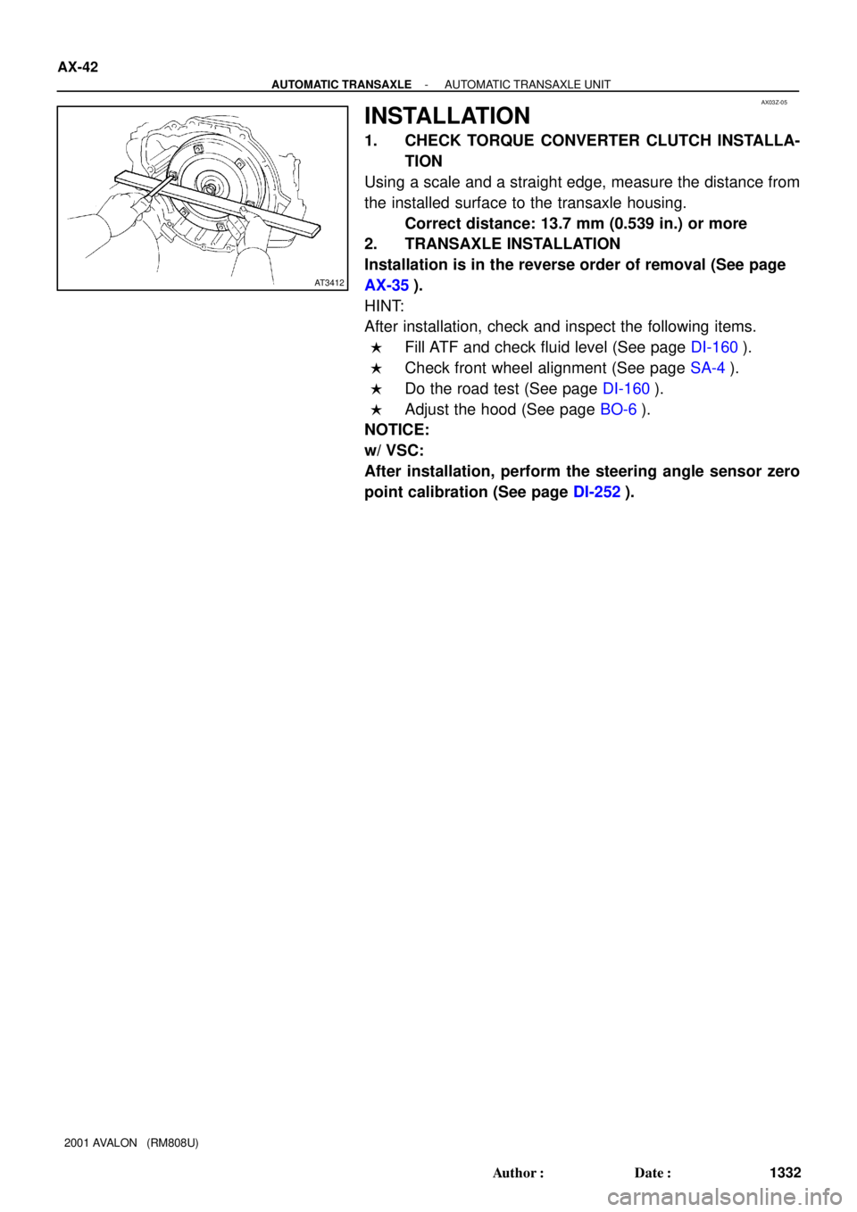
INSTALLATION
1. CHECK TORQUE CONVERTER CLUTCH INSTALLA-
TION
Using a scale and a straight edge, measure the distance from
the installed surface to the transaxle housing.
Correct distance: 13.7 mm (0.539 in.) or more
2. TRANSAXLE INSTALLATION
Installation is in the reverse order of removal (See page
AX-35).
HINT:
After installation, check and inspect the following items.
�Fill ATF and check fluid level (See page DI-160).
�Check front wheel alignment (See page SA-4).
�Do the road test (See page DI-160).
�Adjust the hood (See page BO-6).
NOTICE:
w/ VSC:
After installation, perform the steering angle sensor zero
point calibration (See page DI-252).
Page 100 of 1897
Q06530
Q10038
D07216
Q10037
- AUTOMATIC TRANSAXLEAUTOMATIC TRANSAXLE UNIT
AX-37
1327 Author�: Date�:
2001 AVALON (RM808U)
16. REMOVE EXHAUST MANIFOLD BRACKET MOUNT-
ING BOLT
Torque: 34 N´m (350 kgf´cm, 25 ft´lbf)
17. REMOVE 5 TRANSAXLE-TO-ENGINE BOLTS AND
DISCONNECT GROUND TERMINAL
Torque: 66 N´m (670 kgf´cm, 48 ft´lbf)
18. RAISE AND SUPPORT VEHICLE SECURELY
19. REMOVE LH AND RH FRONT WHEELS
Torque: 103 N´m (1,050 kgf´cm, 76 ft´lbf)
20. REMOVE DIFFERENTIAL FLUID DRAIN PLUG AND
GASKET
Torque: 49 N´m (500 kgf´cm, 36 ft´lbf)
HINT:
At the time of installation, please refer to the following item.
Replace the used gasket with a new gasket.
21. DRAIN DIFFERENTIAL FLUID
22. REMOVE LH AND RH FRONT DRIVE SHAFTS (See
page SA-16)
23. REMOVE ENGINE UNDER COVER
(a) Remove the 6 screws and turn over the front side of the
LH and RH fender liners.
(b) Remove the 2 screws and turn over the rear side of LH
and RH fender liners.
(c) Remove the engine under cover.
Page 377 of 1897

AA
KK
K
K
K
K
K
K
B
L
E
G
GG
G
GG
G
GGI
C
C
C
C
K
K
KKB Instrument Panel Reinforcement
No. 2 Instrument
Panel to Cowl BraceFront Pillar Garnis")
BO2PU-02
H12194: Specified torqueN´m (kgf´cm, ft´lbf)
AA
KK
K
K
K
K
K
K
B
L
E
G
GG
G
GG
G
GGI
C
C
C
C
K
K
KKB Instrument Panel Reinforcement
No. 2 Instrument
Panel to Cowl BraceFront Pillar Garnish
Upper Cluster Finish Panel
Instrument Panel
Safety Pad Front Pillar GarnishNo. 1 Heater to
Register Duct
Instrument Panel
to Cowl BraceSpeaker Opening
Cover Assembly
H
H
H
H
H
H
III
G
D EDD
Steering Wheel
Floor shift:
Rear Console Box Floor shift:
Front Console Box
Combination Switch No. 1 Lower PanelLH Lower Insert
Column shift:
Finish Panel Hood Lock
Release LeverNo. 2 Under Cover
Floor shift:
Console Box
Plate
Steering Wheel Pad Steering Column
Cover
Floor shift:
Front Ash Receptacle
Floor shift:
Upper Console PanelLower Finish
Panel Column shift:
Lower Cover LH Register
TAIWAN:
Center Cluster
Finish Panel
TAIWAN:
Opening Covers with
Heater Control Assembly Radio Assembly with Heater
Control AssemblyLower Panel
Cluster Finish Panel
End Finish Panel Combination Meter Lower Cluster
Finish PanelGlove Compartment
Door Finish Plate
Speaker Opening
Cover Assembly
No. 2 Heater to
Register Duct
No. 1 Register
Floor shift:
Cup Holder
Multi Information
Display
Floor shift:
Under Rear
Console Panel
I
HH
50 (510, 37)
20 (204, 15)
N
JJJJConsole Box Hole Cover
Column shift:
Front Ash Receptacle
- BODYINSTRUMENT PANEL
BO-87
1872 Author�: Date�:
2001 AVALON (RM808U)
INSTRUMENT PANEL
COMPONENTS
Page 388 of 1897

AA
KK
K
K
K
K
K
K
B
L
E
G
GG
G
GG
G
GGI
C
C
C
C
K
K
KKB Instrument Panel Reinforcement
No. 2 Instrument
Panel to Cowl BraceFront Pillar Garnis")
BO2PU-02
H12194: Specified torqueN´m (kgf´cm, ft´lbf)
AA
KK
K
K
K
K
K
K
B
L
E
G
GG
G
GG
G
GGI
C
C
C
C
K
K
KKB Instrument Panel Reinforcement
No. 2 Instrument
Panel to Cowl BraceFront Pillar Garnish
Upper Cluster Finish Panel
Instrument Panel
Safety Pad Front Pillar GarnishNo. 1 Heater to
Register Duct
Instrument Panel
to Cowl BraceSpeaker Opening
Cover Assembly
H
H
H
H
H
H
III
G
D EDD
Steering Wheel
Floor shift:
Rear Console Box Floor shift:
Front Console Box
Combination Switch No. 1 Lower PanelLH Lower Insert
Column shift:
Finish Panel Hood Lock
Release LeverNo. 2 Under Cover
Floor shift:
Console Box
Plate
Steering Wheel Pad Steering Column
Cover
Floor shift:
Front Ash Receptacle
Floor shift:
Upper Console PanelLower Finish
Panel Column shift:
Lower Cover LH Register
TAIWAN:
Center Cluster
Finish Panel
TAIWAN:
Opening Covers with
Heater Control Assembly Radio Assembly with Heater
Control AssemblyLower Panel
Cluster Finish Panel
End Finish Panel Combination Meter Lower Cluster
Finish PanelGlove Compartment
Door Finish Plate
Speaker Opening
Cover Assembly
No. 2 Heater to
Register Duct
No. 1 Register
Floor shift:
Cup Holder
Multi Information
Display
Floor shift:
Under Rear
Console Panel
I
HH
50 (510, 37)
20 (204, 15)
N
JJJJConsole Box Hole Cover
Column shift:
Front Ash Receptacle
- BODYINSTRUMENT PANEL
BO-87
1872 Author�: Date�:
2001 AVALON (RM808U)
INSTRUMENT PANEL
COMPONENTS
Page 400 of 1897

BO2OW-02
H15908
Rear SeatbackRear Seat Cushion
Upper Back Silencer
w/ Speaker:
High-mounted Stop Light
Luggage Compartment Door
Luggage Compartment
Weatherstrip
Luggage Compartment
Door Hinge Arm
w/o Speaker:
High-mounted
Stop Light
Rear Seat Belt Bezel
Rear Seat Belt Bezel
LH Roof Side
Inner Garnish
CRS Tether Anchor
Bracket Cover
Package Tray Trim
RH Roof Side Inner GarnishPin
Torsion Bar
Torsion Bar Clamp
RH Inner Luggage
Compartment Trim CoverFront LH Luggage Compartment
Trim Cover
LH Inner Luggage
Compartment Trim Cover
Front Luggage
Compartment
Trim Cover
Luggage Compartment Side Tray
Luggage Compartment
Floor Mat
Luggage Compartment
Side Cover
Luggage Compartment Door
Cover
No. 1 Luggage Compartment
Trim Hook
RH Rear Floor
Finish Side Plate
Rear Floor
Finish Plate
No. 1 Luggage
Compartment Trim Hook
Spare Wheel Cover Clamp
Luggage Compartment
Door Lock Cylinder
Rear Combination
Light
Spare Wheel CoverLH Rear Floor
Finish Side Platex4
x3
Backup Light
Rear Combination Light
Luggage Compartment Door Striker
Backup
Light
x3x4
Luggage Compartment Door LockLicense Plate Light
N´m (kgf´cm, ft´lbf) : Specified torque
7.8 (80, 69 in.´lbf)
7.8 (80, 69 in.´lbf)
Luggage
Compartment
Outside
Garnish
41 (420, 30)
41 (420, 30)
No. 1 Upper Back Panel Hole Cover
Room Partition
Reinforcement
Door Inside
Handle Bezel
5.4 (55, 48 in.´lbf)
Luggage Door Lock
Opener Assembly
5.4 (55, 48 in.´lbf)
BO-30
- BODYLUGGAGE COMPARTMENT DOOR AND HINGE
1815 Author�: Date�:
2001 AVALON (RM808U)
LUGGAGE COMPARTMENT DOOR AND HINGE
COMPONENTS
Page 404 of 1897

REMOVAL
1. REMOVE DOOR INSIDE HANDLE BEZEL
Using a screwdriver, remove th")
BO41D-01
H15909
H12121
2 Clips
Clip
- BODYLUGGAGE COMPARTMENT DOOR AND HINGE
BO-31
1816 Author�: Date�:
2001 AVALON (RM808U)
REMOVAL
1. REMOVE DOOR INSIDE HANDLE BEZEL
Using a screwdriver, remove the door inside handle bezel as
shown in the illustration.
HINT:
Tape the screwdriver tip before use.
2. REMOVE LUGGAGE COMPARTMENT DOOR COVER
Using a clip remover, remove the 15 clips and luggage compart-
ment door cover.
3. REMOVE LUGGAGE COMPARTMENT DOOR
(a) Disconnect the connectors.
(b) Disconnect the clamps of wire harness.
(c) Remove the 4 bolts and luggage compartment door.
Torque: 7.8 N´m (80 kgf´cm, 69 in.´lbf)
4. REMOVE REAR SEAT (See page BO-1 19)
5. REMOVE NO. 1 UPPER BACK PANEL HOLE COVER
6. REMOVE ROOM PARTITION REINFORCEMENT
(a) Remove the 6 nuts.
(b) Remove the 2 bolts and room partition reinforcement.
7. REMOVE FRONT LH LUGGAGE COMPARTMENT
TRIM COVER
8. REMOVE FRONT UPPER LUGGAGE COMPARTMENT
TRIM COVER
9. REMOVE LUGGAGE COMPARTMENT FLOOR MAT
10. REMOVE LH AND RH REAR FLOOR FINISH SIDE
PLATES
(a) Remove the 2 screws and No. 1 luggage compartment
trim hooks.
(b) Remove the 4 clips and rear floor finish side plates.
11. REMOVE LUGGAGE COMPARTMENT SIDE TRAY
12. REMOVE REAR FLOOR FINISH PLATE
(a) Using a clip remover, remove the 2 clips.
(b) Remove the rear floor finish plate.
13. REMOVE LH AND RH INNER LUGGAGE COMPART-
MENT TRIM COVERS
14. REMOVE FRONT LUGGAGE COMPARTMENT TRIM
COVER
15. REMOVE SPARE WHEEL COVER AND CLAMP
16. REMOVE REAR COMBINATION LIGHTS
Page 507 of 1897
(+)
- BRAKEBRAKE FLUID
BR-5
1404 Author�: Date�:
2001 AVALON (RM808U)
(b) While an assistant depresses the pedal, loosen the
bleeder plug until fluid starts to run out. Then")
F10182
SST
F07901
2 1
(-)(+)
- BRAKEBRAKE FLUID
BR-5
1404 Author�: Date�:
2001 AVALON (RM808U)
(b) While an assistant depresses the pedal, loosen the
bleeder plug until fluid starts to run out. Then tighten the
bleeder plug.
(c) Repeat this procedure until there are no more air bubbles
in the fluid.
Bleeder plug tightening torque:
8.3 N´m (85 kgf´cm, 74 in.´lbf)
5. REPEAT PROCEDURE FOR EACH WHEEL
6. w/ VSC:
BLEED PRECHARGE PUMP
CAUTION:
When repairing the brake master cylinder or precharge
pump, bleed the precharge pump of the air.
(a) Install the SST to the reservoir.
SST 09992-00242, 09992-00350
(b) Using SST, apply pressure to the reservoir.
Pressure: 98.1 kpa (1.0 kgf/cm
2, 14.2 psi)
(c) Disconnect the precharge pump connector.
(d) Connect ML+ (2) terminal to the battery positive (+) and
ML- (1) terminal to the battery negative (-), and activate
the precharge pump about 20 seconds.
(e) Remove the SST from the reservoir.
(f) Connect the vinyl tube to the front brake caliper RH, and
loosen the bleeder plug.
(g) Activate the precharge pump again until there are no
more air bubbles in the fluid.
Bleeder plug tightening torque:
8.3 N´m (85 kgf´cm, 74 in.´lbf)
(h) Connect the precharge pump connector.
7. CHECK FLUID LEVEL IN RESERVOIR
Check the fluid level and add fluid if necessary.
Fluid: SAE J1703 or FMVSS No. 116 DOT3
Page 517 of 1897
BR0L3-04
R02840
- BRAKEFRONT BRAKE CALIPER
BR-29
1428 Author�: Date�:
2001 AVALON (RM808U)
REMOVAL
1. REMOVE FRONT WHEEL
Remove the wheel and temporarily fasten the disc with hub
nuts.
Torque: 103 N´m (1,050 kgf´cm, 76 ft´lbf)
2. DISCONNECT FLEXIBLE HOSE
(a) Remove the union bolt and 2 gaskets from the caliper,
then disconnect the flexible hose from the caliper.
Torque: 29 N´m (300 kgf´cm, 22 ft´lbf)
HINT:
At the time of installation, install the flexible hose lock securely
in the lock hole in the caliper.
(b) Use a container to catch the brake fluid as it drains out.
3. REMOVE CALIPER
(a) Remove the 2 installation bolts.
Torque: 34 N´m (350 kgf´cm, 25 ft´lbf)
(b) Remove the caliper from the torque plate.
4. REMOVE 2 BRAKE PADS WITH ANTI- SQUEAL
SHIMS
5. REMOVE 2 PAD SUPPORT PLATES