Page 46 of 1897
AC1N0-02
I12928
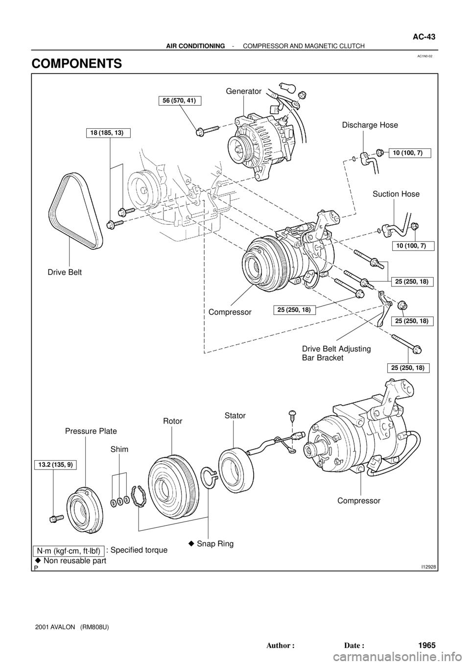
N´m (kgf´cm, ft´lbf): Specified torque
� Non reusable part
Drive Belt
18 (185, 13)
Generator
10 (100, 7)
Discharge Hose
Compressor25 (250, 18)
10 (100, 7)
25 (250, 18)
25 (250, 18)
25 (250, 18)
Compressor
Stator
� Snap Ring Rotor
Shim Pressure Plate
13.2 (135, 9)
Suction Hose
56 (570, 41)
Drive Belt Adjusting
Bar Bracket
- AIR CONDITIONINGCOMPRESSOR AND MAGNETIC CLUTCH
AC-43
1965 Author�: Date�:
2001 AVALON (RM808U)
COMPONENTS
Page 50 of 1897

(B)
AC-50
- AIR CONDITIONINGCOMPRESSOR AND MAGNETIC CLUTCH
1972 Author�: Date�:
2001 AVALON (RM808U)
INSTALLATION
1. INSTALL COMPRESSOR
(a) Install the compressor with 3 nuts.
To")
AC1N4-02
N20259
(A)
(B)
AC-50
- AIR CONDITIONINGCOMPRESSOR AND MAGNETIC CLUTCH
1972 Author�: Date�:
2001 AVALON (RM808U)
INSTALLATION
1. INSTALL COMPRESSOR
(a) Install the compressor with 3 nuts.
Torque: 25 N´m (250 kgf´cm, 18 ft´lbf)
(b) Install the generator drive belt adjusting bar bracket with
2 bolts and a nut.
Torque:
Bolt (A): 18 N´m (185 kgf´cm, 13 ft´lbf)
Bolt (B): 25 N´m (250 kgf´cm, 18 ft´lbf)
Nut: 25 N´m (250 kgf´cm, 18 ft´lbf)
2. INSTALL GENERATOR
(a) Mount generator on the generator bracket with the pivot
bolt and adjusting lock bolt. Do not tighten the bolts yet.
(b) Connect the generator connector.
(c) Connect the generator wire with the nut.
3. CONNECT DISCHARGE AND SUCTION HOSES
Connect both hoses with the bolt and nut.
Torque: 10 N´m (100 kgf´cm, 7 ft´lbf)
NOTICE:
Hoses should be connected immediately after the caps
have been removed.
HINT:
Lubricate 2 new O-ring with compressor oil and install them to
the tube.
4. INSTALL AND CHECK DRIVE BELT
(See page AC-19, AC-17)
5. CONNECT NEGATIVE (-) TERMINAL CABLE TO BAT-
TERY
6. EVACUATE AIR FROM REFRIGERATION SYSTEM
AND CHARGE WITH REFRIGERANT
Specified amount: 600 ± 50 g (21.16 ± 1.76 oz.)
7. INSPECT FOR LEAKAGE OF REFRIGERANT
Using a gas leak detector, check for leakage of refrigerant.
If there is leakage, check the tightening torque at the joints.
8. INSPECT A/C OPERATION
Page 53 of 1897
AC1N1-02
I12935
P19978
N20259
AC-44
- AIR CONDITIONINGCOMPRESSOR AND MAGNETIC CLUTCH
1966 Author�: Date�:
2001 AVALON (RM808U)
REMOVAL
1. RUN ENGINE AT IDLE SPEED WITH A/C ON FOR
APPROX. 10 MINUTES
2. STOP ENGINE
3. DISCONNECT NEGATIVE (- ) TERMINAL CABLE
FROM BATTERY
4. DISCHARGE REFRIGERANT FROM REFRIGERATION
SYSTEM
5. REMOVE DRIVE BELT
(See page AC-18)
6. DISCONNECT DISCHARGE AND SUCTION HOSES
Remove the 2 nuts and disconnect the both hoses.
NOTICE:
Cap the open fittings immediately to keep moisture or dirt
out of the system.
7. REMOVE GENERATOR
(a) Disconnect the generator connector.
(b) Remove the nut, and disconnect the generator wire.
(c) Disconnect the wire harness from the clamp.
(d) Remove the pivot bolt, adjusting lock bolt and generator.
8. REMOVE COMPRESSOR
(a) Disconnect the connector.
(b) Disconnect the wire harness clamp.
(c) Remove the 2 bolts, nut and drive belt adjusting bar
bracket.
Page 64 of 1897
CH0086
Wrong Correct
AC0YF-03
I14032
Generator
Crankshaft PulleyCompressor
N01881
DENSOBorroughs
- AIR CONDITIONINGDRIVE BELT
AC-17
1939 Author�: Date�:
2001 AVALON (RM808U)
DRIVE BELT
ON-VEHICLE INSPECTION
1. INSPECT DRIVE BELT'S INSTALLATION CONDITION
Check that the drive belt fits properly in the ribbed grooves.
2. INSPECT DRIVE BELT TENSION
Using a belt tension gauge, check the drive belt tension.
Drive belt tension:
New belt: 165 ± 22 lbf
Used belt: 88 ± 22 lbf
HINT:
�ºNew beltº refers to a belt which has been used less than
5 minutes on the running engine.
�ºUsed beltº refer to a belt which has been on a running en-
gine for 5 minutes or more.
�After installing the drive belt, check that it fits properly in
the ribbed grooves.
Page 188 of 1897

27 Noise NOISE PRODUCED BY VIBRATION OR SHOCK WHILE DRIVING
No
Ye s Is speaker properly installed?
Noise is produced from static eletricity accumulating in the vehicle body. With vehicles stationary lightly tap each system.
Is noise produced?Install properly.
Each system faulty. Is speaker properly installed?
No
No Ye s
Ye s
28 Noise NOISE PRODUCED WHEN ENGINE STARTS
NoYe s Whistling noise which becomes high-pitched when
accelerator strongly depressed, disappears shortly
after engine stops.Generator noise.
A/C noise.
Fuel gauge noise.
Horn noise.
Ignition noise.
Turn signal noise.
Washer noise.
Engine coolant temp. gauge noise.
Wiper noise. Whining noise occurs when A/C is operating.
Scratching noise occurs during sudden acceleration, driving on rough
roads or when ignition switch is turned ON.
Clicking sound is heard when horn button is pressed, then
released. Whirring/grating sound is heard when pushed
continuously.
Murmuring sound stops when engine stops.
Tick-tack noise occurs in co-ordination with blinking
offlasher.
Noise occurs during window washer operation.
Scratching noise occurs while engine is running,
and continues a while even after engine stops.
Scraping noise in line with wiper beat.
Other type of noiseYe s
Ye s
Ye s
Ye s
Ye s
Ye s
Ye s
Ye s No
No
No
No
No
No
No
No
- BODY ELECTRICALAUDIO SYSTEM
BE-159
1763 Author�: Date�:
2001 AVALON (RM808U)
Page 198 of 1897
No.Wire Connector Side
1
2
3
4
6
7
8
9
10
14
15
16Washer fluid level warning switch
Body ECU
Brake fluid level warning switch
GAUGE Fuse
Lo oil pressure warning switch
ECM
-
TRAC
VSC ECU
Light failure Sensor
-
-
G1
2
3
4
6
7
8
9
10
11
12
13-
Driver's door courtesy switch
DOME Fuse
Cruise ECU
Airbag ECU
ABS&BA&DRAC&VSC ECU
-
Body ECU
Generator L terminal Ignition switch 5 ABS ECU
5 AIR BAG WRN Fuse F
-
- BE-48
- BODY ELECTRICALCOMBINATION METER
1652 Author�: Date�:
2001 AVALON (RM808U)
Page 309 of 1897
 Seat Belt warning light does not light up.
1. Bulb
2. Body Control System
3. Meter Circuit Plate
4. Wire Harness-
DI-6")
- BODY ELECTRICALTROUBLESHOOTING
BE-5
1609 Author�: Date�:
2001 AVALON (RM808U) Seat Belt warning light does not light up.
1. Bulb
2. Body Control System
3. Meter Circuit Plate
4. Wire Harness-
DI-615
BE-53
-
Discharge warning light does not light up.
1. AM2 - Fuse
2. Bulb
3. Meter Circuit Plate
4. Wire Harness
5. Generator-
-
BE-53
-
CH-9
Light Failure warning light does not light up.
1. Bulb
2. Light Failure Sensor
3. Bulb Check Relay
4. Wire Harness
5. Taillight System-
BE-53
BE-53
-
BE-2
Brake warning light does not light up.
1. Bulb
2. Parking Brake Switch
3. Brake Fluid Level Warning Switch
4. Bulb Check Relay
5. Meter Circuit Plate
6. Wire Harness-
BE-53
BE-53
BE-53
BE-43
-
SRS Warning light does not light up.
1. AM2 - Fuse
2. Bulb
3. Airbag Sensor Assembly
4. Meter Circuit Plate
5. Wire Harness-
-
RS-62
RS-67
BE-43
Open Door warning light does not light up.
1. DOME Fuse
2. Bulb
3. Door Courtesy Switch
4. Body Control System
5. Meter Circuit Plate
6. Wire Harness-
-
BE-31
DI-615
BE-43
-
Washer Level warning light does not light up.
1. Bulb
2. Washer Fluid Level Warning Switch
3. Meter Circuit Plate
4. Wire Harness-
BE-53
BE-43
-
COMBINATION METER (Indicator Lights):
SymptomSuspect AreaSee page
O/D OFF indicator light does not light up.
1. Bulb
2. O/D OFF Switch
3. ECM
4. Meter Circuit Plate
5. Wire Harness-
DI-203
DI-1
BE-43
-
Cruise Control indicator light does not light up.
1. Bulb
2. Cruise Control ECU
3. Meter Circuit Plate
4. Wire Harness-
DI-549
BE-43
-
High beam indicator light does not light up.
1. Bulb and Taillight
2. Headlight System
3. Meter Circuit Plate
4. Wire Harness-
BE-2
BE-43
-
Turn indicator light does not light up.
1. Bulb
2. Turn Signal and Hazard Warning System
3. Meter Circuit Plate
4. Wire Harness-
BE-2
BE-43
-
Page 551 of 1897

�After installing a new belt, run the engine")
P19934
Z03473
Ammeter
Voltmeter
BatteryDisconnect Wire
from Terminal B
Generator
- CHARGINGCHARGING SYSTEM
CH-3
1276 Author�: Date�:
2001 AVALON (RM808U)
�After installing a new belt, run the engine for about 5 min-
utes and recheck the belt tension.
6. VISUALLY CHECK GENERATOR WIRING AND
LISTEN FOR ABNORMAL NOISES
(a) Check that the wiring is in good condition.
(b) Check that there is no abnormal noise from the generator
while the engine is running.
7. CHECK DISCHARGE WARNING LIGHT CIRCUIT
(a) Warm up the engine and then turn it off.
(b) Turn off all accessories.
(c) Turn the ignition switch ºONº. Check that the discharge
warning light is lit.
(d) Start the engine. Check that the light goes off.
If the light does not go off as specified, troubleshoot the dis-
charge light circuit.
8. INSPECT CHARGING CIRCUIT WITHOUT LOAD
HINT:
If a battery/generator tester is available, connect the tester to
the charging circuit as per the manufacturer's instructions.
(a) If a tester is not available, connect a voltmeter and amme-
ter to the charging circuit as follows:
�Disconnect the wire from terminal B of the genera-
tor, and connect it to the negative (-) probe of the
ammeter.
�Connect the positive (+) probe of the ammeter to
terminal B of the generator.
�Connect the positive (+) probe of the voltmeter to
terminal B of the generator.
�Ground the negative (-) probe of the voltmeter.
(b) Check the charging circuit as follows:
With the engine running from idling to 2,000 rpm, check
the reading on the ammeter and voltmeter.
Standard amperage: 10 A or less
Standard voltage: 13.2 -14.8 V