Page 1461 of 1897
LU-18
- LUBRICATIONOIL PUMP
1243 Author�: Date�:
2001 AVALON (RM808U)
9. INSTALL ADJUSTING STRUT AND PS PUMP DRIVE
BELT
(a) Temporarily install the adjusting strut with the bolt and nut.
(b) Install the drive belt with the pivot and adjusting bolts.
Torque: 43.1 N´m (440 kgf´cm, 32 ft´lbf)
(c) Tighten the nut.
Torque: 43.1 N´m (440 kgf´cm, 32 ft´lbf)
10. INSTALL A/C COMPRESSOR (See page EM-77)
11. INSTALL GENERATOR (See page CH-1)
12. INSTALL RH FENDER APRON SEAL
13. INSTALL FRONT EXHAUST PIPE (See page EM-77)
14. INSTALL RH FRONT WHEEL
15. FILL ENGINE WITH OIL
16. START ENGINE AND CHECK FOR LEAKS
17. RECHECK ENGINE OIL LEVEL
Page 1463 of 1897
LU0IB-01
P18778
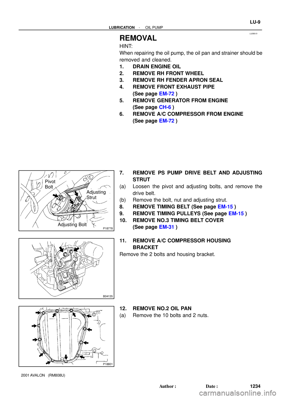
Pivot
Bolt
Adjusting
Strut
Adjusting Bolt
B04135
P18801
- LUBRICATIONOIL PUMP
LU-9
1234 Author�: Date�:
2001 AVALON (RM808U)
REMOVAL
HINT:
When repairing the oil pump, the oil pan and strainer should be
removed and cleaned.
1. DRAIN ENGINE OIL
2. REMOVE RH FRONT WHEEL
3. REMOVE RH FENDER APRON SEAL
4. REMOVE FRONT EXHAUST PIPE
(See page EM-72)
5. REMOVE GENERATOR FROM ENGINE
(See page CH-6)
6. REMOVE A/C COMPRESSOR FROM ENGINE
(See page EM-72)
7. REMOVE PS PUMP DRIVE BELT AND ADJUSTING
STRUT
(a) Loosen the pivot and adjusting bolts, and remove the
drive belt.
(b) Remove the bolt, nut and adjusting strut.
8. REMOVE TIMING BELT (See page EM-15)
9. REMOVE TIMING PULLEYS (See page EM-15)
10. REMOVE NO.3 TIMING BELT COVER
(See page EM-31)
11. REMOVE A/C COMPRESSOR HOUSING
BRACKET
Remove the 2 bolts and housing bracket.
12. REMOVE NO.2 OIL PAN
(a) Remove the 10 bolts and 2 nuts.
Page 1559 of 1897
SS0ET-02
SS-22
- SERVICE SPECIFICATIONSCHARGING
138 Author�: Date�:
2001 AVALON (RM808U)
CHARGING
SERVICE DATA
BatterySpecific gravity
(Except maintenance-free battery) at 20°C (68°F)
Voltage
(Maintenance-free battery) at 20°C (68°F)
1.25 - 1.29
12.5 - 12.9 V
Drive beltTension
New belt
Used belt
175 ± 5 lbf
115 ± 20 lbf
GeneratorRated output
Rotor coil resistance at 20°C (68°F)
Slip ring diameter STD
Minimum
Brush exposed length STD
Minimum12 V 100 A
2.1 - 2.5 W
14.2 - 14.4 mm (0.559 - 0.567 in.)
12.8 mm (0.504 in.)
10.5 mm (0.413 in.)
1.5 mm (0.059 in.)
Voltage regulatorRegulating voltage13.2 - 14.8 V
Page 1560 of 1897
SS0EU-02
- SERVICE SPECIFICATIONSCHARGING
SS-23
139 Author�: Date�:
2001 AVALON (RM808U)
TORQUE SPECIFICATION
Part tightenedN´mkgf´cmft´lbf
Bearing retainer x Drive end frame3.03127 in.´lbf
Rectifier end frame x Drive end frame4.54640 in.´lbf
Cord clamp x Rectifier end frame5.45548 in.´lbf
Generator pulley x Rotor110.51,12581
Rectifier holder x Coil lead on rectifier end frame2.93026 in.´lbf
Voltage regulator and brush holder x Rectifier end frame2.02018 in.´lbf
Plate terminal x Rectifier holder3.93935 in.´lbf
Rear end cover x Rectifier holder4.44539 in.´lbf
Terminal insulator x Rectifier holder4.14236 in.´lbf
Generator x Generator bracket5657041
Generator x Adjusting bar1818013
Generator wire x Generator9.810086 in.´lbf
Page 1567 of 1897

TORQUE SPECIFICATION
Part tightenedN´mkgf´cmft´lbf
Timing belt plate x Oil pump88069 in.´lbf
No.1")
SS0EG-02
- SERVICE SPECIFICATIONSENGINE MECHANICAL
SS-9
125 Author�: Date�:
2001 AVALON (RM808U)
TORQUE SPECIFICATION
Part tightenedN´mkgf´cmft´lbf
Timing belt plate x Oil pump88069 in.´lbf
No.1 idler pulley x Oil pump3435025
No.2 idler pulley x No.2 idler pulley bracket4344032
Camshaft timing pulley x Camshaft
for SST125
881,300
90094
65
Timing belt tensioner x Oil pump2728020
RH engine mounting bracket x Cylinder block2829021
No.2 timing belt cover x No.3 timing belt cover8.58574 in.´lbf
No.1 timing belt cover x Oil pump8.58574 in.´lbf
Crankshaft pulley x Crankshaft2152,200159
No.2 generator bracket x Engine RH mounting bracket2829021
Cylinder head x Cylinder block 12 pointed head 1st
2nd
Recessed head54
Turn 90°
18.5550
Turn 90°
18540
Turn 90°
13
Camshaft bearing cap x Cylinder head1616012
Cylinder head cover x Cylinder head88069 in.´lbf
Exhaust manifold x Cylinder head4950036
Exhaust manifold stay x Exhaust manifold California
Except California34
20350
20025
15
Exhaust manifold stay x Transmission housing California
Except California34
20350
20025
15
No.1 EGR pipe x RH exhaust manifold121209
No.1 EGR pipe x EGR cooler121209
PS pump bracket x RH cylinder head4344032
Oil dipstick guide x LH cylinder head88069 in.´lbf
Water inlet pipe x LH cylinder head19.520014
Cylinder head rear plate x LH cylinder head88069 in.´lbf
No.3 timing belt cover x Cylinder head8.58574 in.´lbf
Water outlet x Intake manifold1515011
Fuel inlet hose x Fuel filter2930021
Intake manifold x Cylinder head1515011
Air intake chamber x Intake manifold4344032
No.2 EGR pipe x Air intake chamber121209
No.2 EGR pipe x EGR cooler121209
No.1 engine hanger x Air intake chamber3940029
No.1 engine hanger x RH cylinder head3940029
Air intake chamber stay x Air intake chamber19.520014
Air intake chamber stay x RH cylinder head19.520014
Main bearing cap x Cylinder block 12 pointed head 1st
2nd
6 pointed head22
Turn 90°
27225
Turn 90°
27516
Turn 90°
20
Connecting rod cap x Connecting rod 1st
2nd24.5
Turn 90°250
Turn 90°18
Turn 90°
Rear oil seal retainer x Cylinder block88069 in.´lbf
EGR cooler x Cylinder block99078 in.´lbf
Page 1568 of 1897
 Engine coolant drain union x Cylinder block
3940029
Water seal plate x Cylinder block1818013
Oil filter union")
SS-10
- SERVICE SPECIFICATIONSENGINE MECHANICAL
126 Author�: Date�:
2001 AVALON (RM808U) Engine coolant drain union x Cylinder block
3940029
Water seal plate x Cylinder block1818013
Oil filter union x Cylinder block3031022
Water inlet housing x Cylinder block88069 in.´lbf
Knock sensor x Cylinder block3940029
No.2 idler pulley bracket x Cylinder block2829021
A/C compressor housing bracket x Cylinder block2525018
Generator bracket x Cylinder block4344032
Drive plate x Crankshaft8385061
Transaxle x Engine6465047
No.1 oil pan x Transaxle37.238027
Drive plate x Torque convertor clutch4142030
Flywheel housing under cover x Transaxle7.88069 in.´lbf
Rear engine mounting insulator x Cylinder block6465047
Front engine mounting insulator x Cylinder block6465047
Engine moving control rod x RH engine mounting bracket6465047
Engine moving control rod x RH fender apron6465047
RH engine mounting stay x Water outlet3232023
RH engine mounting stay x Engine moving control rod3232023
RH engine mounting stay x No.2 RH engine mounting bracket3232023
Front engine mounting insulator x Front frame Silver color bolt
Green color bolt44
66450
67032
49
Engine mounting absorber x Front frame4849035
Engine mounting absorber x Transaxle4849035
Rear engine mounting insulator x Front frame6667048
LH engine mounting insulator x Transaxle6465047
PS pump x PS pump bracket4344031
A/C compressor x Housing bracket25.526019
A/C compressor x No.1 oil pan25.526019
Generator adjusting bar x Drive belt adjusting bar bracket1818513
Fuel inlet hose x Fuel filter2930021
Front exhaust pipe support bracket x No.1 oil pan20.621015
Front exhaust pipe x Exhaust manifold6263046
Front exhaust pipe x Center exhaust pipe5657041
Center exhaust pipe x Tailpipe5657041
Front exhaust pipe bracket x Sub frame3333024
Front exhaust pipe support bracket x Front exhaust pipe stay3333024
Page 1727 of 1897

OPERATION
1. STEERING WHEEL PAD (with AIRBAG)
The inf")
H11878
RS0EF-02
R09725Spiral Cable
H11879
H11880
H11881
- SUPPLEMENTAL RESTRAINT SYSTEMSRS AIRBAG
RS-3
1523 Author�: Date�:
2001 AVALON (RM808U)
OPERATION
1. STEERING WHEEL PAD (with AIRBAG)
The inflater and bag of the SRS are stored in the steering wheel
pad and cannot be disassembled. The inflater contains a squib,
igniter charge, gas generator, etc., and inflates the bag when
instructed by the airbag sensor assembly.
2. SPIRAL CABLE (in COMBINATION SWITCH)
A spiral cable is used as an electrical joint from the vehicle body
side to the steering wheel.
3. FRONT PASSENGER AIRBAG ASSEMBLY
The inflater and bag of the SRS are stored in the front passen-
ger airbag assembly and cannot be disassembled. The inflater
contains a squib, igniter charge, gas generator, etc., and in-
flates the bag when instructed by the airbag sensor assembly.
4. SIDE AIRBAG ASSEMBLY
The inflater and bag of the SRS side airbag are stored in the
side airbag assembly and cannot be disassembled. The inflater
contains a squib, igniter charge, gas generator, etc., and in-
flates the bag when instructed by the side airbag sensor assem-
bly.
5. SEAT BELT PRETENSIONER
The seat belt pretensioner system is a component of the front
seat outer belt. The pretensioner contains a squib, gas genera-
tor, wire, piston, etc., and operates in the event of a frontal colli-
sion. The seat belt pretensioner cannot be disassembled.