Page 1367 of 1897

15. CONNECT ENGINE WIRE TO CABIN
(a) Push in the engine wire through the cowl panel. Install the
grommet.")
S04497
A07300
- ENGINE MECHANICALENGINE UNIT
EM-79
1063 Author�: Date�:
2001 AVALON (RM808U)
15. CONNECT ENGINE WIRE TO CABIN
(a) Push in the engine wire through the cowl panel. Install the
grommet.
(b) Connect the 5 engine ECM connectors.
(c) Install the glove compartment.
16. CONNECT CONNECTORS, CABLE, CLAMPS AND
HOSES
(a) Connect the noise filter connector on the LH fender
apron.
(b) Connect the generator connector and wire.
(c) Connect the starter connector and wire.
(d) Connect the 2 ground strap connectors to the RH fender
apron
(e) Connect the strap connector to the LH fender apron with
the bolt.
(f) Connect the ground cable to the battery body bracket.
(g) Connect the engine wire protector clamp to the battery
body bracket.
(h) Connect the engine wire clamp to the bracket on the RH
fender apron.
(i) Connect the brake booster vacuum hose to the throttle
body.
(j) Connect the engine coolant reservoir hose to the water
outlet.
(k) Connect the heater hose to the intake manifold.
(l) Connect the heater hose to the water inlet housing.
(m) Connect the fuel inlet hose to the fuel filter.
CAUTION:
Perform connecting operations of the fuel tube connector
(quick type) after observing the precautions.
(See page SF-1)
(n) Connect the EVAP hose assembly to the pipe on the
emission control valve set.
(o) Connect the 2 vacuum hoses to the vacuum tank for the
ACIS.
17. INSTALL FRONT EXHAUST PIPE
(a) Temporarily install 3 new gaskets and the front exhaust
pipe with the 2 bolts, 2 compression springs and 4 nuts.
(b) Tighten the 4 nuts holding the exhaust manifolds to the
front exhaust pipe.
Torque: 62 N´m (630 kgf´cm, 46 ft´lbf)
(c) Tighten the 2 bolts and 2 compression springs holding the
front exhaust pipe to the center exhaust pipe.
Torque: 43 N´m (440 kgf´cm, 32 ft´lbf)
Page 1377 of 1897
EM03Y-03
A10834
RH Fender Apron Seal
Generator Drive Belt
Engine Moving
Control Rod
No.2 RH Engine
Mounting Bracket
Ground Strap
Connector PS Pump Drive Belt
Engine Coolant Reservoir Hose
: Specified torque
64 (650, 47)
32 (320, 23)
N´m (kgf´cm, ft´lbf)
- ENGINE MECHANICALTIMING BELT
EM-13
997 Author�: Date�:
2001 AVALON (RM808U)
TIMING BELT
COMPONENTS
Page 1378 of 1897
A06659
No.2 Timing Belt CoverTiming Belt
Timing Belt Guide
No.2 Generator
Bracket RH Engine Mounting Bracket
Crankshaft
PulleyGasket
Engine Wire
Protector
RH Camshaft Timing Pulley
No.2 Idler Pulley
Crankshaft
Timing PulleyDust Boot
Timing Belt Plate Plate Washer
�
215 (2,200, 159)
43 (440, 32)
27 (280, 20)
Timing Belt Tensioner
N´m (kgf´cm, ft´lbf) : Specified torque
� Non-reusable part
28 (290, 21)
No.1 Timing Belt Cover
125 (1,300, 94)
*88 (900, 65)
LH Camshaft
Timing Pulley
No.1 Idler Pulley
34 (350, 25)
� Precoated part
* For use with SST
125 (1,300, 94)
EM-14
- ENGINE MECHANICALTIMING BELT
998 Author�: Date�:
2001 AVALON (RM808U)
Page 1385 of 1897

Join
Line
Join
Line
Length = 460 mm
(18.11 in.)
A04693
SST
P18816
- ENGINE MECHANICALTIMING BELT
EM-25
1009 Author�: Date�:
2001 AVALON (RM808U)
14. INSTALL NO.1 TI")
P12982
Length = 240 mm (9.45 in.)
Join
Line
Join
Line
Length = 460 mm
(18.11 in.)
A04693
SST
P18816
- ENGINE MECHANICALTIMING BELT
EM-25
1009 Author�: Date�:
2001 AVALON (RM808U)
14. INSTALL NO.1 TIMING BELT COVER
(a) Check that the timing belt cover gaskets have cracks or
peeling, etc.
If the gasket has cracks or peeling, etc., replace it using these
steps:
�Using a screwdriver and gasket scraper, remove all
the old gasket material.
�Thoroughly clean all components to remove all the
loose material.
�Remove the backing paper from a new gasket and
install the gasket evenly to the part of the timing belt
cover shaded black in the illustration.
NOTICE:
When joining 2 gaskets, do not leave a gap between them.
Cut off any excess gasket.
�After installing the gasket, press down on it so that
the adhesive firmly sticks to the timing belt cover.
(b) Install the timing belt cover with the 4 bolts.
Torque: 8.5 N´m (85 kgf´cm, 74 in.´lbf)
15. INSTALL CRANKSHAFT PULLEY
(a) Align the pulley set key with the key groove of the pulley,
and slide on the pulley.
(b) Using SST, install the pulley bolt.
SST 09213-54015 (91651-60855), 09330-00021
Torque: 215 N´m (2,200 kgf´cm, 159 ft´lbf)
16. INSTALL NO.2 GENERATOR BRACKET
Install the generator bracket with the pivot bolt and nut. Do not
tighten the bolt yet.
Torque: (Nut): 28 N´m (290 kgf´cm, 21 ft´lbf)
17. INSTALL NO.2 RH ENGINE MOUNTING BRACKET
AND ENGINE MOVING CONTROL ROD
(See page EM-77)
18. CONNECT GROUND STRAP CONNECTORS
19. CONNECT ENGINE COOLANT RESERVOIR HOSE TO
WATER OUTLET
20. INSTALL PS PUMP DRIVE BELT
21. INSTALL GENERATOR DRIVE BELT
(See page CH-16)
22. INSTALL RH FENDER APRON SEAL
23. INSTALL RH FRONT WHEEL
24. VEHICLE ROAD TEST
Check for abnormal noise, shock, slippage, correct shift points
and smoothly operation.
Page 1386 of 1897
EM03Z-03
P18754
P18816
P18817
SST
P18819
SST
- ENGINE MECHANICALTIMING BELT
EM-15
999 Author�: Date�:
2001 AVALON (RM808U)
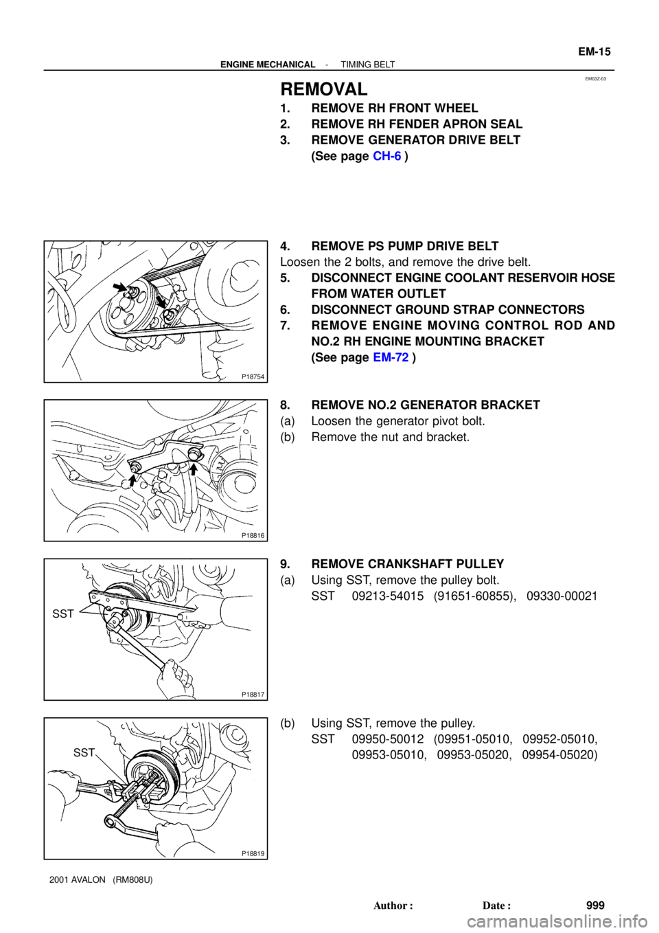
REMOVAL
1. REMOVE RH FRONT WHEEL
2. REMOVE RH FENDER APRON SEAL
3. REMOVE GENERATOR DRIVE BELT
(See page CH-6)
4. REMOVE PS PUMP DRIVE BELT
Loosen the 2 bolts, and remove the drive belt.
5. DISCONNECT ENGINE COOLANT RESERVOIR HOSE
FROM WATER OUTLET
6. DISCONNECT GROUND STRAP CONNECTORS
7. REMOVE ENGINE MOVING CONTROL ROD AND
NO.2 RH ENGINE MOUNTING BRACKET
(See page EM-72)
8. REMOVE NO.2 GENERATOR BRACKET
(a) Loosen the generator pivot bolt.
(b) Remove the nut and bracket.
9. REMOVE CRANKSHAFT PULLEY
(a) Using SST, remove the pulley bolt.
SST 09213-54015 (91651-60855), 09330-00021
(b) Using SST, remove the pulley.
SST 09950-50012 (09951-05010, 09952-05010,
09953-05010, 09953-05020, 09954-05020)
Page 1445 of 1897

GLOSSARY OF SAE AND TOYOTA TERMS
This glossary lists all SAE-J1930 terms and abbreviations used in this manual in complianc")
IN0CI-02
IN-40
- INTRODUCTIONTERMS
40 Author�: Date�:
2001 AVALON (RM808U)
GLOSSARY OF SAE AND TOYOTA TERMS
This glossary lists all SAE-J1930 terms and abbreviations used in this manual in compliance with SAE rec-
ommendations, as well as their TOYOTA equivalents.
SAE
ABBREVIATIONSSAE TERMSTOYOTA TERMS
( )--ABBREVIATIONS
A/CAir ConditioningAir Conditioner
ACLAir CleanerAir Cleaner, A/CL
AIRSecondary Air InjectionAir Injection (AI)
APAccelerator Pedal-
B+Battery Positive Voltage+B, Battery Voltage
BAROBarometric PressureHAC
CACCharge Air CoolerIntercooler
CARBCarburetorCarburetor
CFIContinuous Fuel Injection-
CKPCrankshaft PositionCrank Angle
CLClosed LoopClosed Loop
CMPCamshaft PositionCam Angle
CPPClutch Pedal Position-
CTOXContinuous Trap Oxidizer-
CTPClosed Throttle PositionLL ON, Idle ON
DFIDirect Fuel Injection (Diesel)Direct Injection (DI)
DIDistributor Ignition-
DLC1
DLC2
DLC3Data Link Connector 1
Data Link Connector 2
Data Link Connector 31: Check Connector
2: Total Diagnosis Comunication Link (TDCL)
3: OBD II Diagnostic Connector
DTCDiagnostic Trouble CodeDiagnostic Code
DTMDiagnostic Test Mode-
ECLEngine Control Level-
ECMEngine Control ModuleEngine ECU (Electronic Control Unit)
ECTEngine Coolant TemperatureCoolant Temperature, Water Temperature (THW)
EEPROMElectrically Erasable Programmable Read Only Memory
Electrically Erasable Programmable Read Only Memory
(EEPROM),
Erasable Programmable Read Only Memory (EPROM)
EFEEarly Fuel EvaporationCold Mixture Heater (CMH), Heat Control Valve (HCV)
EGRExhaust Gas RecirculationExhaust Gas Recirculation (EGR)
EIElectronic IgnitionTOYOTA Distributorless Ignition (TDI)
EMEngine ModificationEngine Modification (EM)
EPROMErasable Programmable Read Only MemoryProgrammable Read Only Memory (PROM)
EVAPEvaporative EmissionEvaporative Emission Control (EVAP)
FCFan Control-
FEEPROMFlash Electrically Erasable Programmable
Read Only Memory-
FEPROMFlash Erasable Programmable Read Only Memory-
FFFlexible Fuel-
FPFuel PumpFuel Pump
GENGeneratorAlternator
GNDGroundGround (GND)
Page 1452 of 1897
LU01R-04
B09034
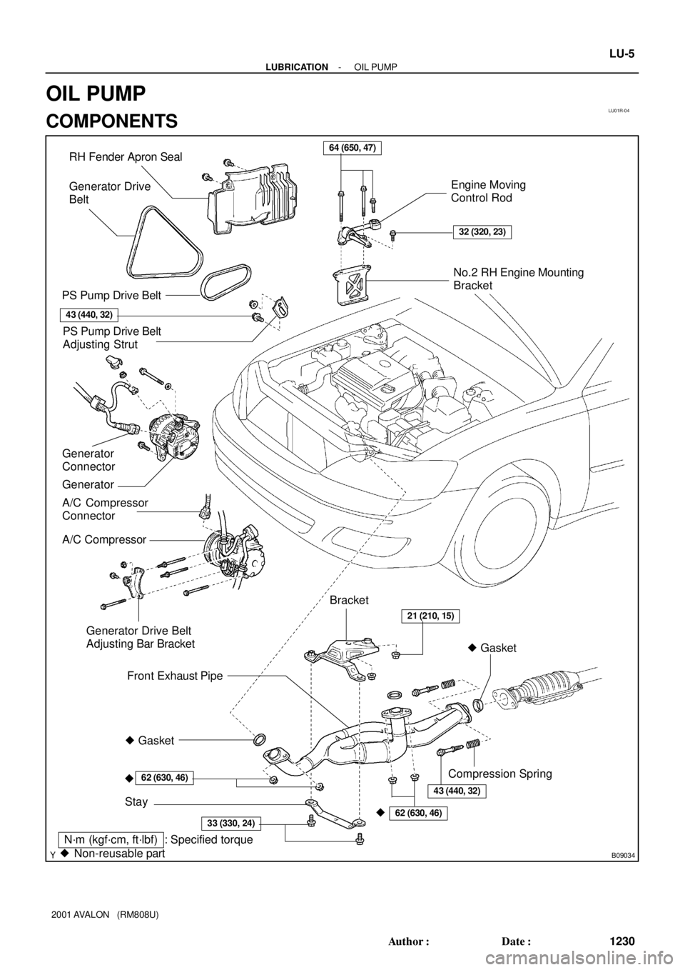
� Gasket RH Fender Apron Seal
PS Pump Drive Belt
A/C Compressor
Connector
A/C CompressorEngine Moving
Control Rod
No.2 RH Engine Mounting
Bracket
Front Exhaust Pipe
Stay
�
PS Pump Drive Belt
Adjusting Strut
Generator Drive Belt
Adjusting Bar Bracket
� Gasket
�
62 (630, 46)
33 (330, 24)
21 (210, 15)
64 (650, 47)
32 (320, 23)
62 (630, 46)
N´m (kgf´cm, ft´lbf) : Specified torque
� Non-reusable partBracket Generator Drive
Belt
43 (440, 32)
Compression Spring
Generator Generator
Connector
43 (440, 32)
- LUBRICATIONOIL PUMP
LU-5
1230 Author�: Date�:
2001 AVALON (RM808U)
OIL PUMP
COMPONENTS
Page 1453 of 1897
B06519
B08672
No.2 Timing Belt CoverTiming Belt
Timing Belt Guide
No.2 Generator
Bracket RH Engine Mounting Bracket
Crankshaft
PulleyGasket
Engine Wire
Protector
RH Camshaft Timing Pulley
No.2 Idler Pulley
Crankshaft
Timing PulleyDust Boot
Timing Belt Plate Plate Washer
�
215 (2,200, 159)
43 (440, 32)
27 (280, 20)
Timing Belt TensionerN´m (kgf´cm, ft´lbf) : Specified torque
� Non-reusable part
28 (290, 21)
No.1 Timing Belt Cover
125 (1,300, 94)
*88 (900, 65)
LH Camshaft
Timing Pulley
No.1 Idler Pulley
34 (350, 25)
� Precoated part
* For use with SST
125 (1,300, 94)
LU-6
- LUBRICATIONOIL PUMP
1231 Author�: Date�:
2001 AVALON (RM808U)