Page 194 of 1897

I12781
: Fuel receiver gauge
: Engine coolant temperature gauge
: Tachometer F
E
T
F
E
T
P
R
N
D
2
L
IlluminationB2 A11
A
No.Wire Connector Side
1
2
3
4
6
7
8
9
10
11
12
13
14
15
16
1
2
3
4
5
6
7
8
9
10
11
12
13 BPark/Neutral position switch (P position)
Park/Neutral position switch (R position)
Park/Neutral position switch (N position)
Park/Neutral position switch (D position)
Park/Neutral position switch (2 position)
Park/Neutral position switch (L position)
O/D main switch
-
Turn signal switch (Right)
Turn signal switch (Left)
Headlight dimmer switch
-
ECU-B Fuse
ECU-IG Fuse
F (PANEL) Fuse
-
Multi-information display meter
- 17
18
19
20
21-
-
Rheostat Light Control Volume
Ground
Ground
22
Theft Deterrent ECU
14
15
16-
-
17
18-
- Combination meter:
A15
A22
A9
A10
A1
A2
A3
A4
A5
A6
A16S
E
2
PROMA20 A12
B3
B4
B5
B6
B8
B9
B11
B12
B13
B14
B10
A7
A21
A19Multi
Information
Display
Fuel level warning
O/D off indicator
Security indicator
Left turn indicator
: Speedometer
S
Hi-beam indicator
A14
Right turn indicatorMulti-information display meter
Multi-information display meter
Multi-information display meter
Multi-information display meter
Multi-information display meter
Multi-information display meter
Multi-information display meter
Multi-information display meter
Multi-information display meter
Multi-information display meter
Multi-information display meter 5
HEAD-LP Fuse BE-44
- BODY ELECTRICALCOMBINATION METER
1648 Author�: Date�:
2001 AVALON (RM808U)
Page 208 of 1897

Z05730
BatteryIgnition
SwitchWarning Light
21
54 3
Z14203
Engine Coolant Temperature Gauge
Ignition
Switch
BatterySender
Gauge
Z15788
Engine Coolant Temperature Gauge
Ignition
Switch
BatteryTest Bulb
(3.4 W)
Wire Harness Side
1
I13322
A
DC
B BE-58
- BODY ELECTRICALCOMBINATION METER
1662 Author�: Date�:
2001 AVALON (RM808U)
12. INSPECT FUEL LEVEL WARNING LIGHT
(a) Disconnect the connector from the sender gauge.
(b) Connect terminals 1 and 3 on the wire harness side con-
nector.
(c) Turn the ignition switch ON, check that the warning light
lights up.
If the warning light does not light up, test the bulb or inspect wire
harness.
13. INSPECT ENGINE COOLANT TEMPERATURE RE-
CEIVER GAUGE OPERATION
(a) Disconnect the connector from the sender gauge.
(b) Turn the ignition switch ON, check that the receiver gauge
needle indicates COOL.
(c) Ground terminal on the wire harness side connector
through a 3.4 W test bulb.
(d) Turn the ignition switch ON, check that the bulb lights up
and the receiver gauge needle moves toward the hot
side.
If operation is as specified, replace the sender gauge.
Then recheck the system.
If operation is not as specified, measure the receiver gauge re-
sistance.
14. INSPECT ENGINE COOLANT TEMPERATURE RE-
CEIVER GAUGE RESISTANCE
Measure the resistance between terminals with fixing pointer to
the stopper.
Tester connectionResistance (W)
A - B250
C - D250
If resistance value is not as specified, replace the receiver
gauge.
Page 308 of 1897

COMBINATION METER (Meter, Gauges and Illumination):
SymptomSuspect AreaSee page
Tachometer, Fuel Gauge and Engine Cool")
BE-4
- BODY ELECTRICALTROUBLESHOOTING
1608 Author�: Date�:
2001 AVALON (RM808U)
COMBINATION METER (Meter, Gauges and Illumination):
SymptomSuspect AreaSee page
Tachometer, Fuel Gauge and Engine Coolant Temperature Gauge
do not operate.
1. ECU-B Fuse
2. ECU-IG No. 2 Fuse
3. Meter Circuit Plate
4. Wire Harness
5. Multi Display-
-
BE-43
-
-
Speedometer does not operate.
1. Vehicle Speed Sensor (ABS - ECU)
2. Meter Circuit Plate
3. Wire Harness
4. Multi DisplayBE-53
BE-43
-
-
Tachometer does not operate.
1. EFI - ECU
2. Meter Circuit Plate
3. Wire Harness
4. Multi Display-
BE-43
-
-
Fuel Gauge does not operate or abnormal operation.
1. Fuel Receiver Gauge
2. Fuel Sender Gauge
3. Meter Circuit Plate
4. Wire HarnessBE-53
BE-53
BE-43
-
Engine Coolant Temperature Gauge does not operate or abnormal
operation.
1. Engine Coolant Temperature Receiver Gauge
2. Engine Coolant Temperature Sender Gauge
3. Meter Circuit Plate
4. Wire HarnessBE-53
BE-53
BE-43
-
All illumination lights do not light up.
1. Bulb
2. PANEL Fuse
3. Light Control Rheostat
4. Wire Harness-
-
BE-53
-
Brightness does not change even when rheostat turned.
1. Bulb
2. Rheostat
3. Wire Harness-
-
-
Only one illumination light does not light up.1. Bulb
2. Wire Harness-
-
COMBINATION METER (Warning Lights):
SymptomSuspect AreaSee page
Warning lights do not light up. (Except Discharge, Open Door and
SRS)
1. Bulb
2. GAUGE No. 1 Fuse
3. Meter Circuit Plate
4. Wire Harness-
-
BE-53
-
Low Oil Pressure warning light does not light up.
1. Multi Display
2. Bulb
3. Low Oil Pressure Warning Switch
4. Meter Circuit Plate
5. Wire Harness-
-
BE-53
BE-43
-
Fuel Level warning light does not light up.
1. Multi Display
2. Bulb
3. Fuel Sender Gause
4. Meter Circuit Plate
5. Wire Harness-
-
BE-53
BE-43
-
ABS warning light does not light up.
1. Bulb
2. ABS ECU
3. Wire Harness-
DI-210
-
Page 568 of 1897
CO02K-03
- COOLINGCOOLANT
CO-1
1194 Author�: Date�:
2001 AVALON (RM808U)
COOLANT
INSPECTION
1. CHECK ENGINE COOLANT LEVEL AT RADIATOR RESERVOIR
The engine coolant level should be between the ºLOWº and ºFULLº lines, when the engine is cold.
If low, check for leaks and add ''Toyota Long Life Coolantº or Equivalent up to the ºFULLº line.
2. CHECK ENGINE COOLANT QUALITY
(a) Remove the radiator cap from the water outlet.
CAUTION:
To avoid the danger of being burned, do not remove the radiator cap while the engine and radiator
are still hot, as fluid and steam can be blown out under pressure.
(b) There should not be any excessive deposits of rust or scale around the radiator cap or water outlet
filler hole, and the coolant should be free from oil.
If excessively dirty, clean the coolant passages and replace the coolant.
(c) Reinstall the radiator cap.
Page 587 of 1897

REMOVAL
HINT:
At the time of installation, please refer to the following items.
�Start the engine, and check for coo")
CO0WT-01
B09040
- COOLINGRADIATOR
CO-17
1210 Author�: Date�:
2001 AVALON (RM808U)
REMOVAL
HINT:
At the time of installation, please refer to the following items.
�Start the engine, and check for coolant and A/T fluid
leaks.
�Check the A/T fluid level (See page DI-160).
1. REMOVE BATTERY AND BATTERY TRAY
2. REMOVE ENGINE UNDER COVER
3. DRAIN ENGINE COOLANT
4. DISCONNECT NO.3 ENGINE ROOM RELAY BLOCK
FROM RADIATOR
5. DISCONNECT NO.1 COOLING FAN CONNECTOR
6. DISCONNECT WIRE CLAMPS FROM NO.1 FAN
SHROUD
7. DISCONNECT NO.2 COOLING FAN CONNECTOR
8. DISCONNECT NO.1 ECT SWITCH WIRE CONNECTOR
9. DISCONNECT WIRE CLAMPS FROM NO.2 FAN
SHROUD
10. DISCONNECT UPPER RADIATOR HOSE FROM RA-
DIATOR
11. DISCONNECT LOWER RADIATOR HOSE FROM RA-
DIATOR
12. DISCONNECT A/T OIL COOLER HOSES FROM RA-
DIATOR
13. REMOVE RADIATOR AND COOLING FANS AS-
SEMBLY
(a) Remove the 2 bolts and 2 upper supports.
Torque: 12.8 N´m (130 kgf´cm, 9 ft´lbf)
(b) Lift out the radiator, and remove the radiator and cooling
fans assembly.
(c) Remove the 2 lower supports.
14. REMOVE NO.1 ECT SWITCH
15. REMOVE NO.1 COOLING FAN FROM RADIATOR
Remove the 2 bolts and cooling fan.
Torque: 5.0 N´m (50 kgf´cm, 44 in.´lbf)
16. REMOVE NO.2 COOLING FAN FROM RADIATOR
Remove the 2 bolts and cooling fan.
Torque: 5.0 N´m (50 kgf´cm, 44 in.´lbf)
Page 590 of 1897

INSTALLATION
1. PLACE THERMOSTAT IN WATER PUMP
(a) Install a new gasket on to the th")
CO02T-03
B04153Stud BoltJiggle Valve
15°15°
CO-12
- COOLINGTHERMOSTAT
1205 Author�: Date�:
2001 AVALON (RM808U)
INSTALLATION
1. PLACE THERMOSTAT IN WATER PUMP
(a) Install a new gasket on to the thermostat.
(b) Align the thermostat jiggle valve with the upper stud bolt,
and insert the thermostat in the water inlet housing.
HINT:
The jiggle valve may be set within 15° of either side of the pre-
scribed position.
2. INSTALL WATER INLET
Install the water inlet with the 3 nuts.
Torque: 8 N´m (80 kgf´cm, 69 in.´lbf)
3. INSTALL WATER INLET PIPE
(a) Install a new O-ring to the water inlet pipe.
(b) Apply soapy water to the O-ring.
(c) Connect the water inlet pipe to the water inlet.
(d) Install the bolt holding the water inlet pipe to the LH cylin-
der head.
Torque: 19.5 N´m (200 kgf´cm, 14 ft´lbf)
4. INSTALL ENGINE WIRE PROTECTOR
5. CONNECT NO.2 ECT SWITCH CONNECTOR
6. CONNECT HEATER HOSES
7. REINSTALL AIR CLEANER HOSE WITH RESONATOR
8. INSTALL V-BANK COVER
(a) Using 5 mm hexagon wrench, install the V-bank cover
with the 3 cap nuts.
(b) Press down the V-bank cover fastener.
9. FILL WITH ENGINE COOLANT
10. START ENGINE AND CHECK FOR LEAKS
11. RECHECK ENGINE COOLANT LEVEL
Page 596 of 1897
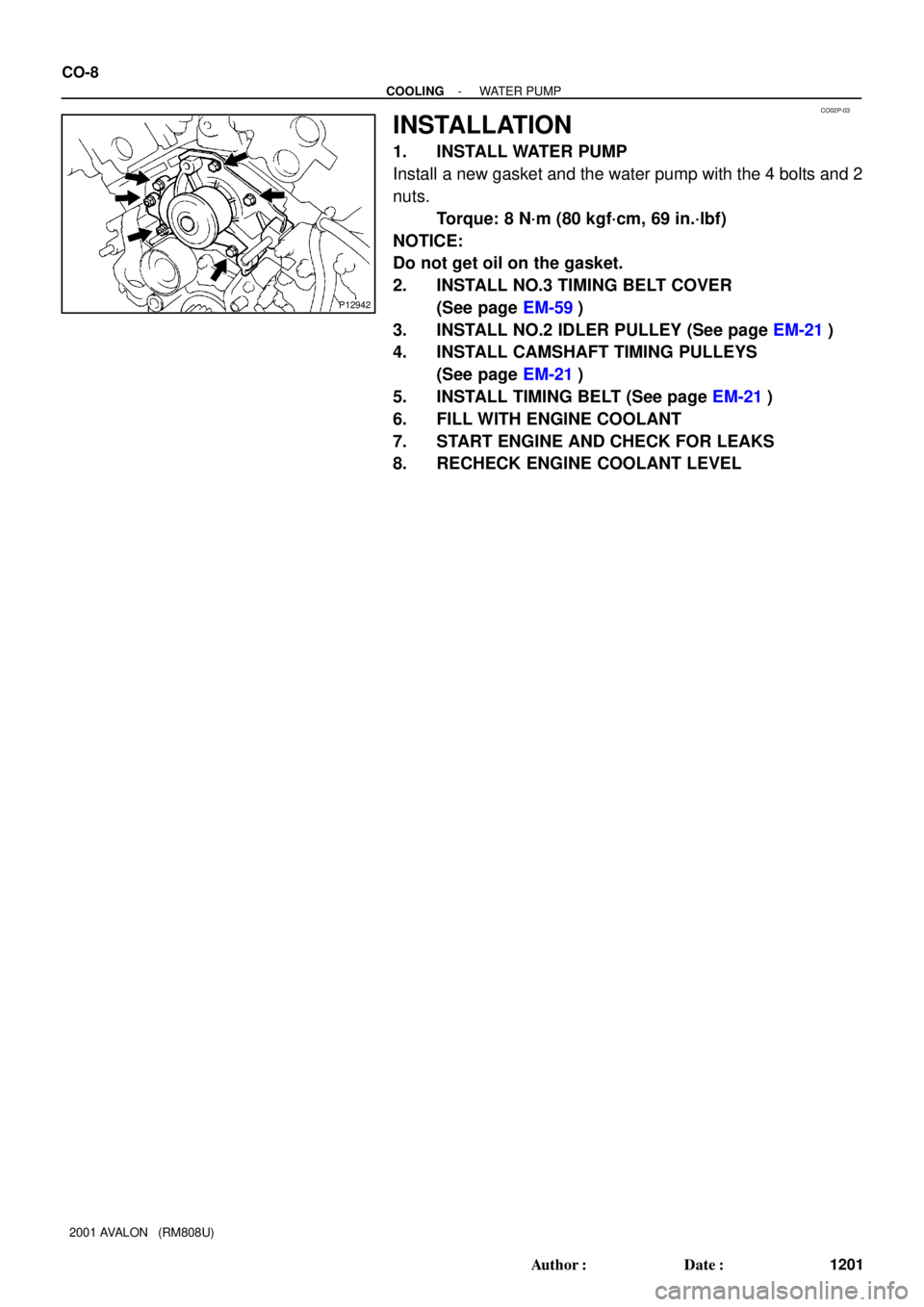
CO02P-03
P12942
CO-8
- COOLINGWATER PUMP
1201 Author�: Date�:
2001 AVALON (RM808U)
INSTALLATION
1. INSTALL WATER PUMP
Install a new gasket and the water pump with the 4 bolts and 2
nuts.
Torque: 8 N´m (80 kgf´cm, 69 in.´lbf)
NOTICE:
Do not get oil on the gasket.
2. INSTALL NO.3 TIMING BELT COVER
(See page EM-59)
3. INSTALL NO.2 IDLER PULLEY (See page EM-21)
4. INSTALL CAMSHAFT TIMING PULLEYS
(See page EM-21)
5. INSTALL TIMING BELT (See page EM-21)
6. FILL WITH ENGINE COOLANT
7. START ENGINE AND CHECK FOR LEAKS
8. RECHECK ENGINE COOLANT LEVEL
Page 1345 of 1897

(n) Install the PS pressure tube with the 2 nuts.
(o) Connect the throttle position sensor connector.
(p) Connect the")
- ENGINE MECHANICALCYLINDER HEAD
EM-69
1053 Author�: Date�:
2001 AVALON (RM808U)
(n) Install the PS pressure tube with the 2 nuts.
(o) Connect the throttle position sensor connector.
(p) Connect the IAC valve connector.
(q) Connect the No.1 VSV connector for the ACIS.
(r) Connect the No.2 VSV connector for the ACIS.
(s) Connect the VSV connecter for the EVAP.
(t) Connect the DLC1 to the bracket on the intake air control
valve.
(u) Connect the throttle cable.
(v) Connect the accelerator cable.
29. INSTALL AIR CLEANER CAP HOSE WITH RESONA-
TOR
30. INSTALL V-BANK COVER
(a) Using a 5 mm hexagon wrench, install the V-bank cover
with the 3 cap nuts.
(b) Press down the V-bank cover fastener.
31. INSTALL FRONT EXHAUST PIPE (See page EM-77)
32. INSTALL PS PUMP (See page SR-35)
33. INSTALL GENERATOR DRIVE BELT
(See page CH-16)
34. FILL WITH ENGINE COOLANT
35. START ENGINE AND CHECK FOR LEAKS
36. VEHICLE ROAD TEST
Check for abnormal noise, shock, slippage, correct shift points
and smoothly operation.
37. RECHECK ENGINE COOLANT LEVEL