Page 593 of 1897
B06475
No.2 Timing Belt CoverTiming Belt
Gasket
Timing Belt Guide
No.2 Generator
Bracket RH Engine Mounting Bracket
28 (290, 21)
Crankshaft
Pulley
215 (2,200, 159)
Gasket
Engine Wire Protector
125 (1,300, 94)
*88 (900, 65)
RH Camshaft Timing Pulley
43 (400, 32)
No.2 Idler Pulley
125 (1,300, 94)
Dust Boot
Timing Belt Tensioner
27 (280, 20)
� Non-reusable part
*For use with SSTNo.1 Timing Belt Cover
LH Camshaft
Timing Pulley
N´m (kgf´cm, ft´lbf) : Specified torque
CO-4
- COOLINGWATER PUMP
1197 Author�: Date�:
2001 AVALON (RM808U)
Page 594 of 1897
B06476� Non-reusable partNo.3 Timing Belt CoverGasket
Collar
Bushing
Water Pump� Gasket Engine Wire
8.5 (65, 74 in.´lbf)
x 6
8 (80, 69 in.´lbf)
N´m (kgf´cm, ft´lbf) : Specified torque
- COOLINGWATER PUMP
CO-5
1198 Author�: Date�:
2001 AVALON (RM808U)
Page 595 of 1897
CO02O-03
P12487
- COOLINGWATER PUMP
CO-7
1200 Author�: Date�:
2001 AVALON (RM808U)
INSPECTION
1. INSPECT WATER PUMP
(a) Visually check the drain hole for coolant leakage.
If leakage is found, replace the water pump.
(b) Turn the pulley, and check that the water pump bearing
moves smoothly and quietly.
If necessary, replace the water pump.
2. INSPECT TIMING BELT COMPONENTS
(See page EM-19)
Page 596 of 1897
CO02P-03
P12942
CO-8
- COOLINGWATER PUMP
1201 Author�: Date�:
2001 AVALON (RM808U)
INSTALLATION
1. INSTALL WATER PUMP
Install a new gasket and the water pump with the 4 bolts and 2
nuts.
Torque: 8 N´m (80 kgf´cm, 69 in.´lbf)
NOTICE:
Do not get oil on the gasket.
2. INSTALL NO.3 TIMING BELT COVER
(See page EM-59)
3. INSTALL NO.2 IDLER PULLEY (See page EM-21)
4. INSTALL CAMSHAFT TIMING PULLEYS
(See page EM-21)
5. INSTALL TIMING BELT (See page EM-21)
6. FILL WITH ENGINE COOLANT
7. START ENGINE AND CHECK FOR LEAKS
8. RECHECK ENGINE COOLANT LEVEL
Page 597 of 1897
CO0WS-01
P12942
CO-6
- COOLINGWATER PUMP
1199 Author�: Date�:
2001 AVALON (RM808U)
REMOVAL
1. DRAIN ENGINE COOLANT
2. REMOVE TIMING BELT (See page EM-15)
3. REMOVE CAMSHAFT TIMING PULLEYS
(See page EM-15)
4. REMOVE NO.2 IDLER PULLEY (See page EM-31)
5. REMOVE NO.3 TIMING BELT COVER
(See page EM-15)
6. REMOVE WATER PUMP
Remove the 4 bolts, 2 nuts, water pump and gasket.
Page 1005 of 1897

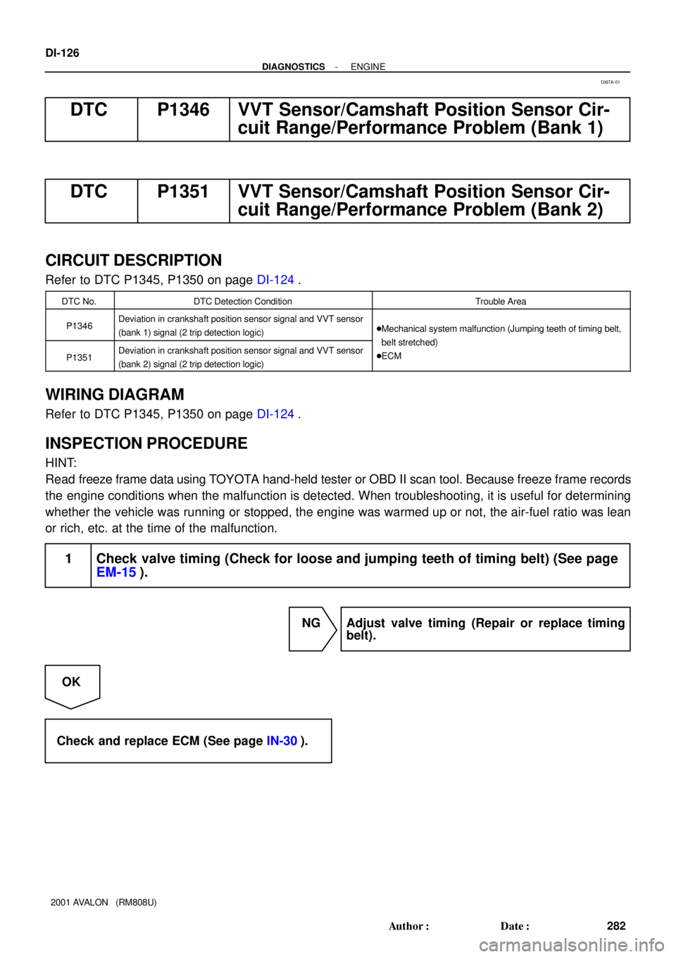
DI-126
- DIAGNOSTICSENGINE
282 Author�: Date�:
2001 AVALON (RM808U)
DTC P1346 VVT Sensor/Camshaft Position Sensor Cir-
cuit Range/Performance Problem (Bank 1)
DTC P1351 VVT Sensor/Camshaft Position Sensor Cir-
cuit Range/Performance Problem (Bank 2)
CIRCUIT DESCRIPTION
Refer to DTC P1345, P1350 on page DI-124.
DTC No.DTC Detection ConditionTrouble Area
P1346Deviation in crankshaft position sensor signal and VVT sensor
(bank 1) signal (2 trip detection logic)�Mechanical system malfunction (Jumping teeth of timing belt,
blt t thd)
P1351Deviation in crankshaft position sensor signal and VVT sensor
(bank 2) signal (2 trip detection logic)belt stretched)
�ECM
WIRING DIAGRAM
Refer to DTC P1345, P1350 on page DI-124.
INSPECTION PROCEDURE
HINT:
Read freeze frame data using TOYOTA hand-held tester or OBD II scan tool. Because freeze frame records
the engine conditions when the malfunction is detected. When troubleshooting, it is useful for determining
whether the vehicle was running or stopped, the engine was warmed up or not, the air-fuel ratio was lean
or rich, etc. at the time of the malfunction.
1 Check valve timing (Check for loose and jumping teeth of timing belt) (See page
EM-15).
NG Adjust valve timing (Repair or replace timing
belt).
OK
Check and replace ECM (See page IN-30).
DI6TA-01
Page 1008 of 1897
- DIAGNOSTICSENGINE
DI-129
285 Author�: Date�:
2001 AVALON (RM808U)
OK
4 Check VVT controller assembly.
PREPARATION:
(a) Remove the timing belt (See page EM-15).
(b) Remove the cylinder head cover.
(c) Remove the OCV (See page EM-31).
(d) Drain oil into the VVT controller assembly (See page EM-31).
CHECK:
Check whether the oil into VVT controller assembly is drained or not.
OK:
The oil into VVT controller assembly is drained.
NG Replace VVT controller assembly, and then go
to step 5.
OK
5 Check OCV (See page SF-51).
NG Replace OCV, and then go to step 6.
OK
6 Check blockage of OCV, oil check valve and oil pipe No.1.
NG Repair or replace.
OK
7 Check whether or not DTC P1349/P1354 is stored.
PREPARATION:
(a) Clear the DTC (See page DI-3).
(b) Perform simulation test.
Page 1011 of 1897
DI-132
- DIAGNOSTICSENGINE
288 Author�: Date�:
2001 AVALON (RM808U)
Check and replace ECM (See page IN-30).
4 Check VVT controller assembly.
PREPARATION:
(a) Remove the timing belt (See page EM-15).
(b) Remove the cylinder head cover.
(c) Remove the OCV (See page EM-31).
(d) Drain oil into the VVT controller assembly (See page EM-31).
CHECK:
Check whether the oil into VVT controller assembly is drained or not.
OK:
The oil into VVT controller assembly is drained.
NG Replace VVT controller assembly, and then go
to step 5.
OK
5 Check OCV (See page SF-51).
NG Replace OCV, and then go to step 6.
OK
6 Check blockage of OCV, oil check valve and oil pipe No.1.
NG Repair or replace.
OK
7 Check whether or not DTC P1349/P1354 is stored.
PREPARATION:
(a) Clear the DTC (See page DI-3).
(b) Perform simulation test.