Page 383 of 1897

BO2PV-01
H12176
2 Clips
H121774 Clips
H12178
4 Clips
H12181
BO-90
- BODYINSTRUMENT PANEL
1875 Author�: Date�:
2001 AVALON (RM808U)
REMOVAL
1. REMOVE FRONT SEATS
(See page BO-105 or BO-1 12)
2. REMOVE FRONT DOOR WEATHERSTRIPS
3. REMOVE FRONT PILLAR GARNISHES
4. REMOVE STEERING WHEEL PAD
(See page SR-12)
5. REMOVE COLUMN COVERS
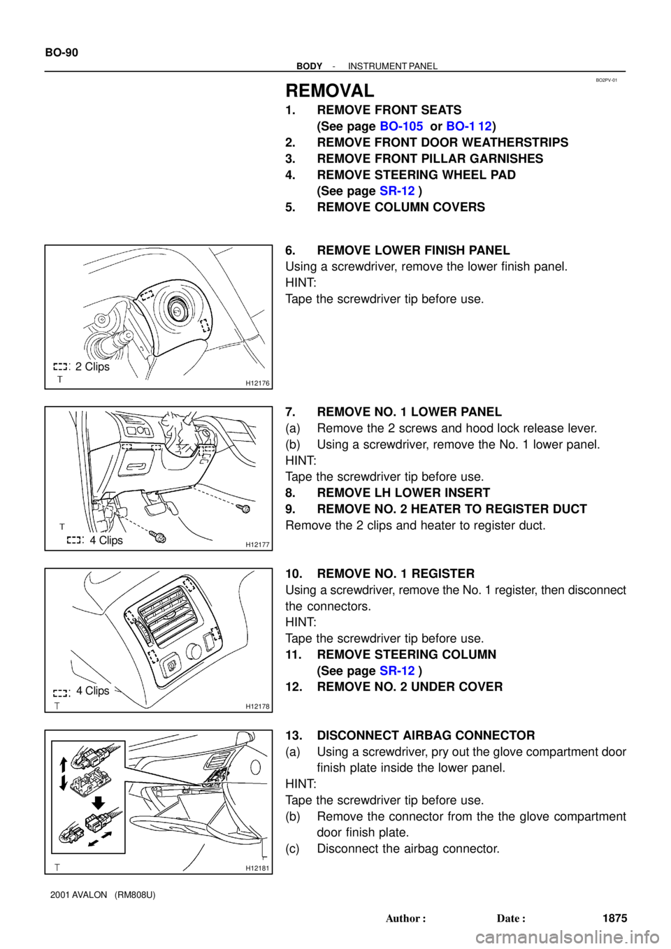
6. REMOVE LOWER FINISH PANEL
Using a screwdriver, remove the lower finish panel.
HINT:
Tape the screwdriver tip before use.
7. REMOVE NO. 1 LOWER PANEL
(a) Remove the 2 screws and hood lock release lever.
(b) Using a screwdriver, remove the No. 1 lower panel.
HINT:
Tape the screwdriver tip before use.
8. REMOVE LH LOWER INSERT
9. REMOVE NO. 2 HEATER TO REGISTER DUCT
Remove the 2 clips and heater to register duct.
10. REMOVE NO. 1 REGISTER
Using a screwdriver, remove the No. 1 register, then disconnect
the connectors.
HINT:
Tape the screwdriver tip before use.
11. REMOVE STEERING COLUMN
(See page SR-12)
12. REMOVE NO. 2 UNDER COVER
13. DISCONNECT AIRBAG CONNECTOR
(a) Using a screwdriver, pry out the glove compartment door
finish plate inside the lower panel.
HINT:
Tape the screwdriver tip before use.
(b) Remove the connector from the the glove compartment
door finish plate.
(c) Disconnect the airbag connector.
Page 394 of 1897

BO2PV-01
H12176
2 Clips
H121774 Clips
H12178
4 Clips
H12181
BO-90
- BODYINSTRUMENT PANEL
1875 Author�: Date�:
2001 AVALON (RM808U)
REMOVAL
1. REMOVE FRONT SEATS
(See page BO-105 or BO-1 12)
2. REMOVE FRONT DOOR WEATHERSTRIPS
3. REMOVE FRONT PILLAR GARNISHES
4. REMOVE STEERING WHEEL PAD
(See page SR-12)
5. REMOVE COLUMN COVERS
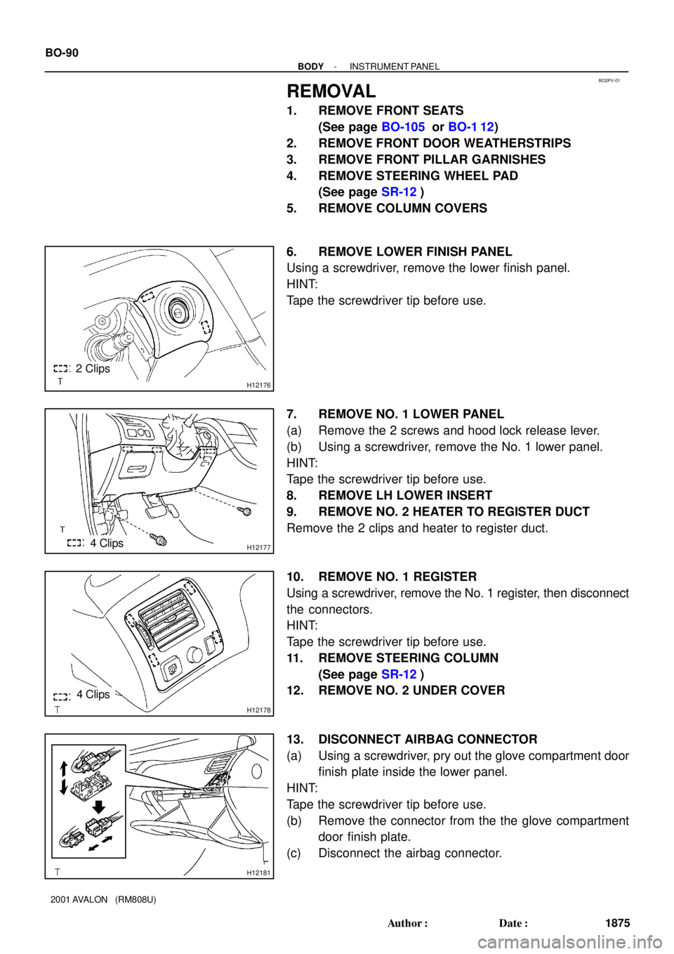
6. REMOVE LOWER FINISH PANEL
Using a screwdriver, remove the lower finish panel.
HINT:
Tape the screwdriver tip before use.
7. REMOVE NO. 1 LOWER PANEL
(a) Remove the 2 screws and hood lock release lever.
(b) Using a screwdriver, remove the No. 1 lower panel.
HINT:
Tape the screwdriver tip before use.
8. REMOVE LH LOWER INSERT
9. REMOVE NO. 2 HEATER TO REGISTER DUCT
Remove the 2 clips and heater to register duct.
10. REMOVE NO. 1 REGISTER
Using a screwdriver, remove the No. 1 register, then disconnect
the connectors.
HINT:
Tape the screwdriver tip before use.
11. REMOVE STEERING COLUMN
(See page SR-12)
12. REMOVE NO. 2 UNDER COVER
13. DISCONNECT AIRBAG CONNECTOR
(a) Using a screwdriver, pry out the glove compartment door
finish plate inside the lower panel.
HINT:
Tape the screwdriver tip before use.
(b) Remove the connector from the the glove compartment
door finish plate.
(c) Disconnect the airbag connector.
Page 675 of 1897

- DIAGNOSTICSABS WITH EBD & BA & TRAC & VSC SYSTEM
DI-294
449 Author�: Date�:
INSPECTION PROCEDURE
HINT:
Start the inspection from step 1 in case of using the TOYOTA hand-held tester and start from step 2 in case
of not using the TOYOTA hand-held tester.
1 Check output value of the steering angle sensor.
PREPARATION:
(a) Connect the TOYOTA hand-held tester to the DLC3.
(b) Turn the ignition switch ON and push the TOYOTA hand-held tester main switch ON.
(c) Select the DATALIST mode on the TOYOTA hand-held tester.
CHECK:
Check that the steering wheel turning angle value of the steering angle sensor displayed on the TOYOTA
hand-held tester is appropriate when turning the steering wheel.
OK:
Steering wheel turning angle value must be appropriate.
OK Go to step 4.
NG
2 Check the installation condition of steering angle sensor and adapter.
NG Repair or replace steering angle sensor (See
page SR-12).
OK
3 Check for open and short circuit in harness and connector between steering
angle sensor, translate ECU and ABS & BA & TRAC & VSC ECU (See page
IN-30).
NG Repair or replace harness or connector.
OK
Page 865 of 1897
N16045
3
4
- DIAGNOSTICSCRUISE CONTROL SYSTEM
DI-591
747 Author�: Date�:
2001 AVALON (RM808U)
2 Check cancel switch continuity.
PREPARATION:
(a) Remove steering wheel center pad (See page SR-12).
(b) Disconnect the control switch connector.
CHECK:
Check continuity between terminals 3 and 4 of control switch
connector when cancel switch is held ON and OFF.
OK:
Switch positionTester connectionSpecified condition
OFF3 - 4No continuity
Hold ON3 - 4Continuity
NG Replace control switch.
OK
3 Check harness and connector between cruise control ECU and cancel switch
(See page IN-30).
NG Repair or replace harness or connector.
OK
Check and replace cruise control ECU (See
page IN-30).
Page 1213 of 1897

H01026H06508H06509
LOCK
Airbag Sensor
Assembly
P Squib
D Squib
P/T Squib (LH)
Side Squib
(LH)
P/T Squib (RH)
Side Squib
(RH)
Spiral
Cable
Side Airbag
Sensor (LH)
Side Airbag
Sensor (RH) Front Airbag
Sensor (LH)
Front Airbag
Sensor (RH)
- DIAGNOSTICSSUPPLEMENTAL RESTRAINT SYSTEM
DI-477
633 Author�: Date�:
2001 AVALON (RM808U)
INSPECTION PROCEDURE
1 Prepare for inspection.
PREPARATION:
(a) Disconnect negative (-) terminal cable from the battery,
and wait at least for 90 seconds.
(b) Remove the steering wheel pad (See page SR-12).
(c) Disconnect the connector of the front passenger airbag
assembly (See page RS-28).
(d) Disconnect the connector of the side airbag assembly RH
and LH (See page RS-42 and RS-56).
(e) Disconnect the connector of the seat belt pretensioner
RH and LH (See page BO-128).
(f) Disconnect the connectors of the airbag sensor assembly
(See page RS-63 and RS-68).
(g) Disconnect the connector of the front airbag sensor RH
and LH (See page RS-73).
(h) Disconnect the connector of the side airbag sensor as-
sembly RH and LH (See page RS-78).
CAUTION:
Store the steering wheel pad, front passenger airbag as-
sembly and side airbag assemlby with the front surface
facing upward.
Page 1743 of 1897

H11891
Connector
AB0163
Wire Harness
Diameter
Stripped Wire Harness Section
H11892
L
M
RS-20
- SUPPLEMENTAL RESTRAINT SYSTEMSTEERING WHEEL PAD AND SPIRAL CABLE
1540 Author�: Date�:
2001 AVALON (RM808U)
(a) Remove the steering wheel pad (See page SR-12).
CAUTION:
�When removing the steering wheel pad, work must be
started 90 seconds after the ignition switch is turned
to the ºLOCKº position and the negative (-) terminal
cable is disconnected from the battery.
�When storing the steering wheel pad, keep the upper
surface of the pad facing upward.
(b) Remove the connector on the rear surface of the steering
wheel pad from the bracket.
(c) Using a service-purpose wire harness tie down the steer-
ing wheel pad to the disc wheel.
Wire harness: Stripped wire harness section
1.25 mm
2
or more (0.0019 in2. or more)
CAUTION:
If a wire harness which is too thin or some other thing is
used to tie down the steering wheel pad, it may be snapped
by the shock when the airbag is deployed. This is highly
dangerous. Always use a wire harness for vehicle use
which is at least 1.25 mm
2
(0.0019 in2.).
HINT:
To calculate the square of the stripped wire harness section:
Square = 3.14 x (Diameter)
2 divided by 4
(1) Install the 2 bolts with washers in the 2 bolt holes in
the steering wheel pad.
Bolt:
L: 35. mm (1.387 in.)
M: 6.0 mm (0.236 in.)
Pitch: 1.0 mm (0.039 in.)
NOTICE:
�Tighten the bolts by hand until the bolts become diffi-
cult to turn.
�Do not tighten the bolts too much.
Page 1747 of 1897
AB0166
RS-24
- SUPPLEMENTAL RESTRAINT SYSTEMSTEERING WHEEL PAD AND SPIRAL CABLE
1544 Author�: Date�:
2001 AVALON (RM808U)
3. DEPLOYMENT WHEN DISPOSING OF STEERING
WHEEL PAD WITH AIRBAG DEPLOYED IN COLLI-
SION
Dispose of the steering wheel pad (with airbag).
CAUTION:
�The steering wheel pad is very hot when the airbag is
deployed, so leave it alone for at least 30 minutes af-
ter deployment.
�When moving a vehicle for scrapping which has a
steering wheel pad with the deployed airbag, use
gloves and safety glasses.
�Use gloves and safety glasses when handling a steer-
ing wheel pad with deployed airbag.
�Always wash your hands with water after completing
the operation.
�Do not apply water, etc. to a steering wheel pad with
deployed airbag.
(1) Remove the steering wheel pad from the steering
wheel (See page SR-12).
(2) Place the steering wheel pad in a vinyl bag, tie the
end tightly and dispose of it in the same way as oth-
er general parts disposal.
Page 1748 of 1897

RS0L4-01
H11878
H11886
H11887
Horn Button
Contact Plate
H11888
- SUPPLEMENTAL RESTRAINT SYSTEMSTEERING WHEEL PAD AND SPIRAL CABLE
RS-15
1535 Author�: Date�:
2001 AVALON (RM808U)
INSPECTION
1. Vehicle not involved in collision:
INSPECT SUPPLEMENTAL RESTRAINT SYSTEM
(a) Do a diagnostic system check (See page DI-349).
(b) Do a visual check which includes the following item with
the steering wheel pad (with airbag) installed in the ve-
hicle.
Check cuts, minute cracks or marked discoloration on the
steering wheel pad top surface and in the grooved por-
tion.
2. Vehicle involved in collision and airbag is not
deployed:
INSPECT SUPPLEMENTAL RESTRAINT SYSTEM
(a) Do a diagnostic system check (See page DI-349).
(b) Do a visual check which includes the following items with
the steering wheel pad (with airbag) removed from the ve-
hicle.
�Check cuts, minute cracks or marked discoloration
on the steering wheel pad top surface and in the
grooved portion.
�Check cuts and cracks in wire harness, and chip-
ping in connectors.
�Check the deformation of the steering wheel.
�Check the deformation of the horn button contact
plate of the steering wheel pad.
HINT:
�If the horn button contact plate of the steering wheel pad
is deformed, never repair it. Always replace the steering
wheel pad with a new one.
�There should be no interference between the steering
wheel pad and steering wheel, and the clearance should
be uniform all the way around when the new steering
wheel pad is installed on the steering wheel.
CAUTION:
For removal and installation of the steering wheel pad, see
page SR-12 and SR-22, be sure to follow the correct proce-
dure.