Page 41 of 1897
AC2G3-01
I12939
- +
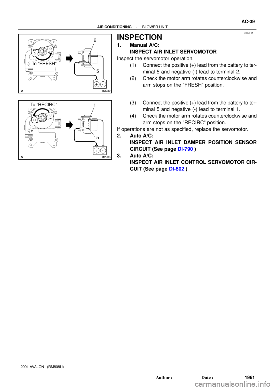
To ºFRESHº
2
5
I12938
- +
To ºRECIRCº1
5
- AIR CONDITIONINGBLOWER UNIT
AC-39
1961 Author�: Date�:
2001 AVALON (RM808U)
INSPECTION
1. Manual A/C:
INSPECT AIR INLET SERVOMOTOR
Inspect the servomotor operation.
(1) Connect the positive (+) lead from the battery to ter-
minal 5 and negative (-) lead to terminal 2.
(2) Check the motor arm rotates counterclockwise and
arm stops on the ºFRESHº position.
(3) Connect the positive (+) lead from the battery to ter-
minal 5 and negative (-) lead to terminal 1.
(4) Check the motor arm rotates counterclockwise and
arm stops on the ºRECIRCº position.
If operations are not as specified, replace the servomotor.
2. Auto A/C:
INSPECT AIR INLET DAMPER POSITION SENSOR
CIRCUIT (See page DI-790)
3. Auto A/C:
INSPECT AIR INLET CONTROL SERVOMOTOR CIR-
CUIT (See page DI-802)
Page 98 of 1897
AX0KA-01
A07441
5 mm
Hexagon
Wrench
D04381
V-bank Cover
Fastener
D07234
Q09982
- AUTOMATIC TRANSAXLEAUTOMATIC TRANSAXLE UNIT
AX-35
1325 Author�: Date�:
2001 AVALON (RM808U)
REMOVAL
1. REMOVE ENGINE HOOD
Torque: 26 N´m (265 kgf´cm, 19 ft´lbf)
2. REMOVE BATTERY
3. REMOVE AIR CLEANER ASSEMBLY
4. REMOVE V-BANK COVER
(a) Using a 5 mm hexagon wrench, remove the 3 cap nuts.
(b) Turn the V-bank cover fastener counterclockwise and
loosen it.
(c) Remove the V-bank cover.
HINT:
At the time of installation, please refer to the following item.
When installing the V-bank cover fastener, remove the fasten-
er once, then position and push in it.
5. REMOVE THROTTLE CABLE FROM THROTTLE
BODY
Torque: 15 N´m (150 kgf´cm, 11 ft´lbf)
6. REMOVE CRUISE CONTROL ACTUATOR
(a) Disconnect the connector.
(b) Remove the 3 bolts and disconnect cruise control actua-
tor with the bracket.
Torque: 13 N´m (130 kgf´cm, 9 ft´lbf)
Page 140 of 1897

TORQUE CONVERTER CLUTCH")
AT0952
SST
AX040-04
AT0953
SST
AT3306
Hold
Lock
Free
Turn
AT2821
- AUTOMATIC TRANSAXLETORQUE CONVERTER CLUTCH AND DRIVE PLATE
AX-43
1333 Author�: Date�:
2001 AVALON (RM808U)
TORQUE CONVERTER CLUTCH
AND DRIVE PLATE
INSPECTION
1. INSPECT ONE-WAY CLUTCH
(a) Install SST into the inner race of the one-way clutch.
SST 09350-32014 (09351-32010)
(b) Install SST so that it fits in the notch of the converter clutch
hub and outer race of the one-way clutch.
SST 09350-32014 (09351-32020)
(c) With the torque converter clutch standing on its side, the
clutch locks when turned counterclockwise, and rotates
freely and smoothly clockwise.
If necessary, clean the converter and retest the clutch.
Replace the converter if the clutch still fails the test.
2. MEASURE DRIVE PLATE RUNOUT AND INSPECT
RING GEAR
(a) Set up a dial indicator, and measure the drive plate run-
out.
(b) Check the damage of the ring gear.
Maximum runout: 0.20 mm (0.0079 in.)
If the runout is not within the specification or ring gear is dam-
aged, replace the drive plate.
Torque: 83 N´m (850 kgf´cm, 61 ft´lbf)
Page 192 of 1897
BE1EJ-01
- BODY ELECTRICALCLOCK
BE-165
1769 Author�: Date�:
2001 AVALON (RM808U)
CLOCK
TROUBLESHOOTING
HINT:
Troubleshoot the clock according to the table below.
ProblemNo.
Clock will not operateBE-53
Clock loses or gains timeBE-53
Page 248 of 1897

12. ADJUST AUTOMATIC LIGHT CONTROL SE")
N12536
ClockwiseCounter Clockwise
I01255
1
2 3 4
From Back Side
- BODY ELECTRICALHEADLIGHT AND TAILLIGHT SYSTEM
BE-21
1625 Author�: Date�:
2001 AVALON (RM808U)
12. ADJUST AUTOMATIC LIGHT CONTROL SENSOR
(a) Adjustment of the light control is performed by turning the
sensitivity knob on the sensor.
(b) This will be determined at what light condition the auto-
matic control will take place.
�If response is too quick, turn the knob counterclock-
wise.
�If response is too slow, turn the knob clockwise.
13. Connector connected:
INSPECT AUTOMATIC LIGHT CONTROL SENSOR
CIRCUIT
Connect the wire harness side connector to the sensor and in-
spect wire harness side connector from the back side, as
shown.
HINT:
�Ignition switch ON.
�Light control switch AUTO.
�Vehicle's surroundings are bright.
Tester connectionConditionSpecified condition
3 - GroundConstantContinuity
1 - GroundIgnition switch LOCK or ACCNo voltage
1 - GroundIgnition switch ON9.5 V or more
Vehicle is under the direct sun light.
(Sensor is not covered)Taillight and Headlight are ON.
If circuit is as specified, try replacing the sensor with a new one.
If the circuit is not as specified, inspect the circuit connected to
other parts.
Page 282 of 1897

(b)
2
112
N21866
21
N21867
2
1
N21865
(a)
(b)
21
1
2
N22086
21
- BODY ELECTRICALPOWER SEAT CONTROL SYSTEM (w/o Driving
Position Memory)BE-109
1713 Author�: Date�:
2001 AVALON (RM808U)
9.")
N21865
(a)
(b)
2
112
N21866
21
N21867
2
1
N21865
(a)
(b)
21
1
2
N22086
21
- BODY ELECTRICALPOWER SEAT CONTROL SYSTEM (w/o Driving
Position Memory)BE-109
1713 Author�: Date�:
2001 AVALON (RM808U)
9. INSPECT SLIDE MOTOR OPERATION
(a) Connect the positive (+) lead from the battery to terminal
1 and the negative (-) lead to terminal 2, check that the
motor turns counterclockwise.
(b) Reverse the polarity, check that the motor turns clock-
wise.
If operation is not as specified, replace the seat adjuster.
10. INSPECT SLIDE MOTOR PTC THERMISTOR OPERA-
TION
( ): Passenger side
(a) Connect the positive (+) lead from the battery to terminal
1 (2), the positive (+) lead from the ammeter to terminal
2 (1) and the negative (-) lead to the battery negative (-)
terminal, then move the seat cushion to the front position.
(b) Continue to apply voltage, check that current changes to
less than 1 ampere within 4 to 90 seconds.
(c) Disconnect the leads from terminals.
(d) Approximately 60 seconds later, connect the positive (+)
lead from the battery to terminal 2 (1) and the negative (-)
lead to terminal 1 (2), check that the seat cushion begins
to move backwards.
If operation is not as specified, replace the seat adjuster.
11. INSPECT FRONT VERTICAL MOTOR OPERATION
(a) Connect the positive (+) lead from the battery to terminal
1 and the negative (-) lead to terminal 2, check that the
motor turns counterclockwise.
(b) Reverse the polarity, check that the motor turns clock-
wise.
If operation is not as specified, replace the seat adjuster.
12. INSPECT FRONT VERTICAL MOTOR PTC THERM-
ISTOR OPERATION
( ): Passenger side
(a) Connect the positive (+) lead from the battery to terminal
1 (2), the positive (+) lead from the ammeter to terminal
2 (1) and the negative (-) lead to the battery negative (-)
terminal, then move the seat cushion to the highest posi-
tion.
(b) Continue to apply voltage, check that the current changes
to less than 1 ampere within 4 to 90 seconds.
Page 283 of 1897

1(b)
2
2
1
N22088
21
N22089
21
N21865
(a)
(b)
2
1
1 2 BE-1 10
- BODY ELECTRICALPOWER SEAT CONTROL SYSTEM (w/o Driving
Position Memory)
1714 Author�: Date�:
2001 AVALON (RM808U)")
N22087
21
N21865
(a)
1(b)
2
2
1
N22088
21
N22089
21
N21865
(a)
(b)
2
1
1 2 BE-1 10
- BODY ELECTRICALPOWER SEAT CONTROL SYSTEM (w/o Driving
Position Memory)
1714 Author�: Date�:
2001 AVALON (RM808U)
(c) Disconnect the leads from the terminals.
(d) Approximately 60 seconds later, connect the positive (+)
lead from the battery to terminal 2 (1) and the negative (-)
lead to terminal 1 (2), check that the seat cushion begins
to descend.
If operation is not as specified, replace the seat adjuster.
13. INSPECT REAR VERTICAL MOTOR OPERATION
(a) Connect the positive (+) lead from the battery to terminal
1 and the negative (-) lead to terminal 2, check that the
motor turns counterclockwise.
(b) Reverse the polarity, check that the motor turns clock-
wise.
If operation is not as specified, replace the seat adjuster.
14. INSPECT REAR VERTICAL MOTOR PTC THERM-
ISTOR OPERATION
(a) Connect the positive (+) lead from the battery to terminal
2 (1), the positive (+) lead from the ammeter to terminal
1 (2) and the negative (-) lead to the battery negative (-)
terminal, then move the seat cushion to the highest posi-
tion.
(b) Continue to apply voltage, check that the current changes
to less than 1 ampere within 4 to 90 seconds.
(c) Disconnect the leads from the terminals.
(d) Approximately 60 seconds later, connect the positive (+)
lead from the battery to terminal 1 (2) and the negative (-)
lead to terminal 2 (1), check that the seat cushion begins
to descend.
If operation is not as specified, replace the seat adjuster.
15. INSPECT RECLINING MOTOR OPERATION
(a) Connect the positive (+) lead from the battery to terminal
1 and the negative (-) lead to terminal 2, check that the
motor turns counterclockwise.
(b) Reverse the polarity, check that the motor turns clock-
wise.
If operation is not as specified, replace the seat adjuster.
Page 289 of 1897

4. INSPECT POWER MAIN RELAY CONTINUITY
C")
I01200
2 1
35
2 5
1 3
I12547
2
1
I12548
21
I12549
1
2
I12550
1
2
BE-74
- BODY ELECTRICALPOWER WINDOW CONTROL SYSTEM
1678 Author�: Date�:
2001 AVALON (RM808U)
4. INSPECT POWER MAIN RELAY CONTINUITY
ConditionTester connectionSpecified condition
Constant1 - 2Continuity
Apply B+ between
terminals 1 and 2.3 - 5Continuity
If continuity is not as specified, replace the relay.
5. Driver 's Door:
INSPECT POWER WINDOW MOTOR OPERATION
(a) Connect the positive (+) lead from the battery to terminal
1 and the negative (-) lead to terminal 2, and check that
the motor turns clockwise.
(b) Reverse the polarity, check that the motor turns counter-
clockwise.
If operation is not as specified, replace the motor.
NOTICE:
Since the jam protection may not work properly be sure to
conduct procedures described in ºHOW TO RESET POW-
ER MOTOR (RESET AND PULSE SWITCH)º after this in-
spection.
6. Front Passenger's Door:
INSPECT POWER WINDOW MOTOR OPERATION
(a) Connect the positive (+) lead from the battery to terminal
2 and the negative (-) lead to terminal 1, and check that
the motor turns clockwise.
(b) Reverse the polarity, check that the motor turns counter-
clockwise.
If operation is not as specified, replace the motor.