Page 1356 of 1897
P12596
P12797
SST
P12590
A05222
FrontRecessed Heat Bolt
8 mm Hexagon Wrench
EM-38
- ENGINE MECHANICALCYLINDER HEAD
1022 Author�: Date�:
2001 AVALON (RM808U)
31. DISASSEMBLE EXHAUST CAMSHAFTS
(a) Mount the hexagonal wrench head portion of the cam-
shaft in a vise.
NOTICE:
Be careful not to damage the camshaft.
(b) Using SST, turn the sub-gear counterclockwise, and re-
move the service bolt.
SST 09960-10010 (09962-01000, 09963-00500)
(c) Using snap ring pliers, remove the snap ring.
(d) Remove the wave washer, camshaft sub-gear, and cam-
shaft gear spring.
HINT:
Arrange the camshaft sub-gears and gear springs (RH and LH
side).
32. REMOVE CYLINDER HEADS
(a) Using an 8 mm hexagon wrench, remove the cylinder
head (recessed head) bolt on each cylinder head, then re-
peat for the other side, as shown.
Page 1359 of 1897

P12802
SST
Z09124
A05739
A05740
- ENGINE MECHANICALCYLINDER HEAD
EM-53
1037 Author�: Date�:
2001 AVALON (RM808U)
(f) Using SST and a hammer, tap in a new guide bushing to
the specified protrusion height.
SST 09201-01055, 09950-70010 (09951-07100)
Protrusion height:
Intake11.1 - 11.3 mm (0.437 - 0.453 in.)
Exhaust8.9 - 9.3 mm - (0.350 - 0.366 in.)
(g) Using a sharp 5.5 mm reamer, ream the guide bushing to
obtain the standard specified clearance (See page
EM-42) between the guide bushing and valve stem.
2. REPLACE CAMSHAFT TIMING GEAR (VVT-i)
NOTICE:
Do not remove or install the camshaft timing gear (VVT-i)
beside changing VVT-i or the camshaft.
(a) Mount the hexagon wrench head portion of the camshaft
in a vise.
NOTICE:
Be careful not to damage the camshaft.
(b) Using a 46 mm socket wrench, remove the lock nut by
turning it clockwise.
NOTICE:
�Remove it under the condition that the lock pin is op-
erated and lock at the maximum delay angle position.
�The lock nut have LH threads.
�Never use any tool other than the socket wrench,
otherwise that may result in deforming the cam angle
rotor portion.
(c) Remove the camshaft VVT-i.
HINT:
In case of having difficulty to remove VVT-i, apply a slight hit-
ting using a plastic-faced hammer and then remove it.
NOTICE:
Never remove the 3 bolts on the gear.
Page 1360 of 1897

A05706
Align
A05738
A05245
A05243
EM-54
- ENGINE MECHANICALCYLINDER HEAD
1038 Author�: Date�:
2001 AVALON (RM808U)
(d) Align the knock pin and knock pin groove and install VVT-
i on the camshaft.
NOTICE:
Install it under the condition that the lock pin is operated
and lock at the maximum delay angle position.
(e) Apply the engine oil on the nut, the placing surface of
VVT-i and the screw portion.
HINT:
Be sure to apply the oil, otherwise the prescribed torque cannot
be obtained.
(f) Using a 46 mm socket wrench, install and torque a new
lock nut by turning it counterclockwise.
Torque: 150 N´m (1,530 kgf´cm, 110 ft´lbf)
NOTICE:
�Must change the nuts to the new ones when to change
VVT-i.
�The lock nut have LH threads.
�Never use any tool other than the socket wrench,
otherwise that may result in deforming the cam angle
rotor portion.
3. REPLACE SPARK PLUG TUBE GASKETS
(a) Bend up the tab on the ventilation baffle plate which pre-
vents the gasket from the slipping out.
(b) Using a screwdriver and hammer, tap out the gasket.
(c) Using needle-nose pliers, pry out the gasket.
Page 1369 of 1897

EM0ZL-02
A10518
5 mm
Hexagon
Wrench
A07300
EM-72
- ENGINE MECHANICALENGINE UNIT
1056 Author�: Date�:
2001 AVALON (RM808U)
REMOVAL
1. REMOVE BATTERY AND TRAY
2. REMOVE HOOD
3. REMOVE ENGINE FENDER APRON SEALS
4. DRAIN ENGINE COOLANT
5. DRAIN ENGINE OIL
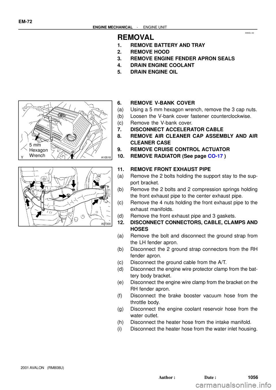
6. REMOVE V-BANK COVER
(a) Using a 5 mm hexagon wrench, remove the 3 cap nuts.
(b) Loosen the V-bank cover fastener counterclockwise.
(c) Remove the V-bank cover.
7. DISCONNECT ACCELERATOR CABLE
8. REMOVE AIR CLEANER CAP ASSEMBLY AND AIR
CLEANER CASE
9. REMOVE CRUISE CONTROL ACTUATOR
10. REMOVE RADIATOR (See page CO-17)
11. REMOVE FRONT EXHAUST PIPE
(a) Remove the 2 bolts holding the support stay to the sup-
port bracket.
(b) Remove the 2 bolts and 2 compression springs holding
the front exhaust pipe to the center exhaust pipe.
(c) Remove the 4 nuts holding the front exhaust pipe to the
exhaust manifolds.
(d) Remove the front exhaust pipe and 3 gaskets.
12. DISCONNECT CONNECTORS, CABLE, CLAMPS AND
HOSES
(a) Remove the bolt and disconnect the ground strap from
the LH fender apron.
(b) Disconnect the 2 ground strap connectors from the RH
fender apron.
(c) Disconnect the ground cable from the A/T.
(d) Disconnect the engine wire protector clamp from the bat-
tery body bracket.
(e) Disconnect the engine wire clamp from the bracket on the
RH fender apron.
(f) Disconnect the brake booster vacuum hose from the
throttle body.
(g) Disconnect the engine coolant reservoir hose from the
water outlet.
(h) Disconnect the heater hose from the intake manifold.
(i) Disconnect the heater hose from the water inlet housing.
Page 1373 of 1897
EM0ZR-02
A10836
� Gasket
� Non-reusable part
N´m (kgf´cm, ft´lbf) : Specified torque� Gasket
� Bracket
Front Exhaust Pipe Heat Insulator
Center Exhaust Pipe� Gasket Heat Insulator
Heated Oxygen Sensor
(Bank 1 Sensor 2)Tailpipe
Ring Ring
33 (330, 24)
Heat Insulator Heated Oxygen Sensor (Bank 1 Sensor 2)
� Before installing the oxygen sensor, twist
the sensor wire counterclockwise 3 and
1/2 turns.
If it is twisted, remove the oxygen sensor
and reinstall it. � After installing the sensor wire is not twisted.HINT:
43 (440, 32)
21 (210, 15)
62 (630, 46)
33 (330, 24)
44 (450, 33)
Stay
Pipe Support
Bracket
39 (400, 29)
22 (220,16)
Pipe Support
Bracket
33 (330, 24)
�62 (630, 46)
43 (440, 32)
Compression Spring
�
�
Compression Spring
Damper
19 (190, 14)
Heat Insulator
No.1 Exhaust Pipe
Support Bracket
Type A
Type B
Ring
Pipe Support
Bracket
EM-1 10
- ENGINE MECHANICALEXHAUST SYSTEM
1094 Author�: Date�:
2001 AVALON (RM808U)
EXHAUST SYSTEM
COMPONENTS
Page 1375 of 1897

A10518
5 mm
Hexagon
Wrench
EM15O-01
A10838
TOYOTA
Hand-Held Tester
DLC3
A10536
Lead Wire
A07285
E1DLC1
TE1
DLC1SST
A05184
EM-10
- ENGINE MECHANICALIGNITION TIMING
994 Author�: Date�:
2001 AVALON (RM808U)
IGNITION TIMING
INSPECTION
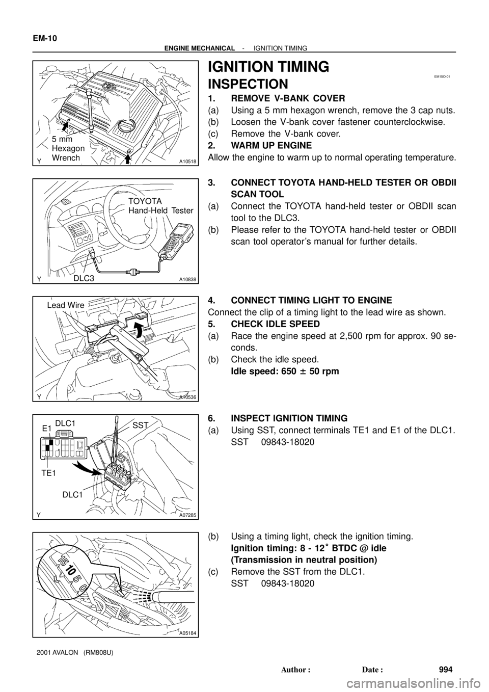
1. REMOVE V-BANK COVER
(a) Using a 5 mm hexagon wrench, remove the 3 cap nuts.
(b) Loosen the V-bank cover fastener counterclockwise.
(c) Remove the V-bank cover.
2. WARM UP ENGINE
Allow the engine to warm up to normal operating temperature.
3. CONNECT TOYOTA HAND-HELD TESTER OR OBDII
SCAN TOOL
(a) Connect the TOYOTA hand-held tester or OBDII scan
tool to the DLC3.
(b) Please refer to the TOYOTA hand-held tester or OBDII
scan tool operator's manual for further details.
4. CONNECT TIMING LIGHT TO ENGINE
Connect the clip of a timing light to the lead wire as shown.
5. CHECK IDLE SPEED
(a) Race the engine speed at 2,500 rpm for approx. 90 se-
conds.
(b) Check the idle speed.
Idle speed: 650 ± 50 rpm
6. INSPECT IGNITION TIMING
(a) Using SST, connect terminals TE1 and E1 of the DLC1.
SST 09843-18020
(b) Using a timing light, check the ignition timing.
Ignition timing: 8 - 12° BTDC @ idle
(Transmission in neutral position)
(c) Remove the SST from the DLC1.
SST 09843-18020
Page 1384 of 1897

P18808
A05052
P12983
Length = 1,410 mm (55.51 in.)
P18815
EM-24
- ENGINE MECHANICALTIMING BELT
1008 Author�: Date�:
2001 AVALON (RM808U)
10. CHECK VALVE TIMING
(a) Slowly turn the crankshaft 2 revolutions, and align the tim-
ing marks of the crankshaft timing pulley and oil pump
body.
NOTICE:
Always turn the crankshaft clockwise.
(b) Check that the timing marks of the RH and LH timing pul-
leys with the timing marks of the No.3 timing belt cover as
shown in the illustration.
If the marks do not align, remove the timing belt and reinstall it.
(c) Remove the crankshaft pulley bolt.
11. INSTALL RH ENGINE MOUNTING BRACKET
Torque: 28 N´m (290 kgf´cm, 21 ft´lbf)
12. INSTALL NO.2 TIMING BELT COVER
(a) Check that the timing belt cover gasket has no cracks or
peeling, etc.
If the gasket has cracks or peeling, etc., replace it using these
steps:
�Using a screwdriver and gasket scraper, remove all
the old gasket material.
�Thoroughly clean all components to remove all the
loose material.
�Remove the backing paper from a new gasket and
install the gasket evenly to the part of the timing belt
cover shaded black in the illustration.
�After installing the gasket, press down on it so that
the adhesive firmly sticks to the timing belt cover.
(b) Install the timing belt cover with the 5 bolts.
Torque: 8.5 N´m (85 kgf´cm, 74 in.´lbf)
(c) Install the engine wire protector clamps to the No.3 timing
belt cover.
13. INSTALL TIMING BELT GUIDE
Install the timing belt guide, facing the cup side outward.
Page 1387 of 1897
P18820
A05050
Clamp
Clamp
P18814
P18808
A05052
EM-16
- ENGINE MECHANICALTIMING BELT
1000 Author�: Date�:
2001 AVALON (RM808U)
10. REMOVE NO.1 TIMING BELT COVER
Remove the 4 bolts and timing belt cover.
11. REMOVE TIMING BELT GUIDE
12. REMOVE NO.2 TIMING BELT COVER
(a) Disconnect the engine wire protector clamps from the
No.3 timing belt cover.
(b) Remove the 5 bolts and timing belt cover.
13. REMOVE RH ENGINE MOUNTING BRACKET
Remove the 2 bolts, nut and mounting bracket.
14. SET NO.1 CYLINDER TO TDC/COMPRESSION
(a) Temporarily install the crankshaft pulley bolt to the crank-
shaft.
(b) Turn the crankshaft, and align the timing marks of the
crankshaft timing pulley and oil pump body.
NOTICE:
Always turn the crankshaft clockwise.
(c) Check that timing marks of the camshaft timing pulleys
and No.3 timing belt cover are aligned.
If not, turn the crankshaft 1 revolution (360°).
(d) Remove the crankshaft pulley bolt.