Page 1384 of 1897

P18815
EM-24
- ENGINE MECHANICALTIMING BELT
1008 Author�: Date�:
2001 AVALON (RM808U)
10. CHECK VALVE TIMING
(a) Slowly turn the crankshaft 2 revol")
P18808
A05052
P12983
Length = 1,410 mm (55.51 in.)
P18815
EM-24
- ENGINE MECHANICALTIMING BELT
1008 Author�: Date�:
2001 AVALON (RM808U)
10. CHECK VALVE TIMING
(a) Slowly turn the crankshaft 2 revolutions, and align the tim-
ing marks of the crankshaft timing pulley and oil pump
body.
NOTICE:
Always turn the crankshaft clockwise.
(b) Check that the timing marks of the RH and LH timing pul-
leys with the timing marks of the No.3 timing belt cover as
shown in the illustration.
If the marks do not align, remove the timing belt and reinstall it.
(c) Remove the crankshaft pulley bolt.
11. INSTALL RH ENGINE MOUNTING BRACKET
Torque: 28 N´m (290 kgf´cm, 21 ft´lbf)
12. INSTALL NO.2 TIMING BELT COVER
(a) Check that the timing belt cover gasket has no cracks or
peeling, etc.
If the gasket has cracks or peeling, etc., replace it using these
steps:
�Using a screwdriver and gasket scraper, remove all
the old gasket material.
�Thoroughly clean all components to remove all the
loose material.
�Remove the backing paper from a new gasket and
install the gasket evenly to the part of the timing belt
cover shaded black in the illustration.
�After installing the gasket, press down on it so that
the adhesive firmly sticks to the timing belt cover.
(b) Install the timing belt cover with the 5 bolts.
Torque: 8.5 N´m (85 kgf´cm, 74 in.´lbf)
(c) Install the engine wire protector clamps to the No.3 timing
belt cover.
13. INSTALL TIMING BELT GUIDE
Install the timing belt guide, facing the cup side outward.
Page 1385 of 1897

Join
Line
Join
Line
Length = 460 mm
(18.11 in.)
A04693
SST
P18816
- ENGINE MECHANICALTIMING BELT
EM-25
1009 Author�: Date�:
2001 AVALON (RM808U)
14. INSTALL NO.1 TI")
P12982
Length = 240 mm (9.45 in.)
Join
Line
Join
Line
Length = 460 mm
(18.11 in.)
A04693
SST
P18816
- ENGINE MECHANICALTIMING BELT
EM-25
1009 Author�: Date�:
2001 AVALON (RM808U)
14. INSTALL NO.1 TIMING BELT COVER
(a) Check that the timing belt cover gaskets have cracks or
peeling, etc.
If the gasket has cracks or peeling, etc., replace it using these
steps:
�Using a screwdriver and gasket scraper, remove all
the old gasket material.
�Thoroughly clean all components to remove all the
loose material.
�Remove the backing paper from a new gasket and
install the gasket evenly to the part of the timing belt
cover shaded black in the illustration.
NOTICE:
When joining 2 gaskets, do not leave a gap between them.
Cut off any excess gasket.
�After installing the gasket, press down on it so that
the adhesive firmly sticks to the timing belt cover.
(b) Install the timing belt cover with the 4 bolts.
Torque: 8.5 N´m (85 kgf´cm, 74 in.´lbf)
15. INSTALL CRANKSHAFT PULLEY
(a) Align the pulley set key with the key groove of the pulley,
and slide on the pulley.
(b) Using SST, install the pulley bolt.
SST 09213-54015 (91651-60855), 09330-00021
Torque: 215 N´m (2,200 kgf´cm, 159 ft´lbf)
16. INSTALL NO.2 GENERATOR BRACKET
Install the generator bracket with the pivot bolt and nut. Do not
tighten the bolt yet.
Torque: (Nut): 28 N´m (290 kgf´cm, 21 ft´lbf)
17. INSTALL NO.2 RH ENGINE MOUNTING BRACKET
AND ENGINE MOVING CONTROL ROD
(See page EM-77)
18. CONNECT GROUND STRAP CONNECTORS
19. CONNECT ENGINE COOLANT RESERVOIR HOSE TO
WATER OUTLET
20. INSTALL PS PUMP DRIVE BELT
21. INSTALL GENERATOR DRIVE BELT
(See page CH-16)
22. INSTALL RH FENDER APRON SEAL
23. INSTALL RH FRONT WHEEL
24. VEHICLE ROAD TEST
Check for abnormal noise, shock, slippage, correct shift points
and smoothly operation.
Page 1386 of 1897
EM03Z-03
P18754
P18816
P18817
SST
P18819
SST
- ENGINE MECHANICALTIMING BELT
EM-15
999 Author�: Date�:
2001 AVALON (RM808U)
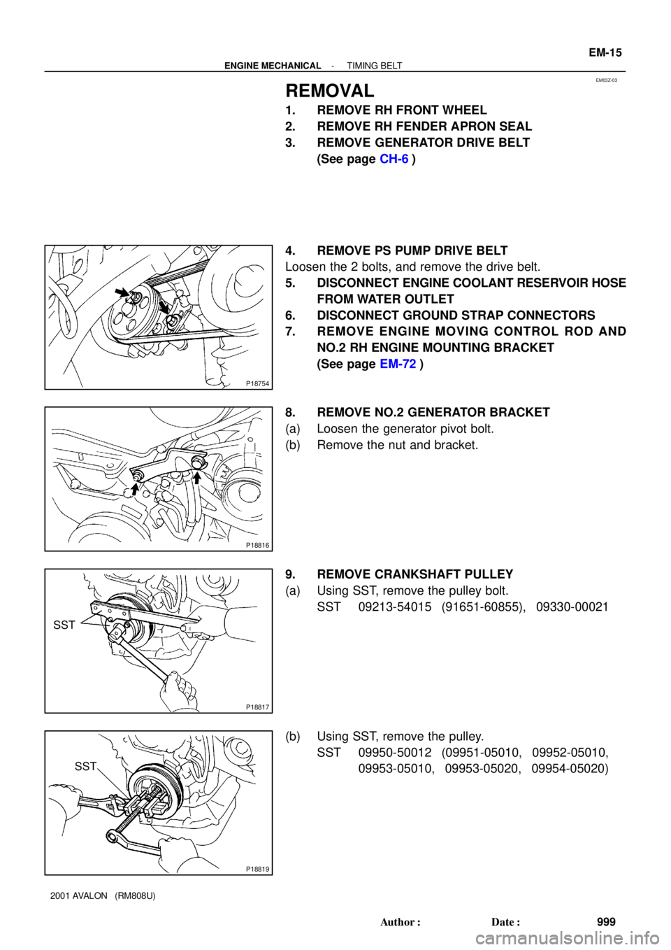
REMOVAL
1. REMOVE RH FRONT WHEEL
2. REMOVE RH FENDER APRON SEAL
3. REMOVE GENERATOR DRIVE BELT
(See page CH-6)
4. REMOVE PS PUMP DRIVE BELT
Loosen the 2 bolts, and remove the drive belt.
5. DISCONNECT ENGINE COOLANT RESERVOIR HOSE
FROM WATER OUTLET
6. DISCONNECT GROUND STRAP CONNECTORS
7. REMOVE ENGINE MOVING CONTROL ROD AND
NO.2 RH ENGINE MOUNTING BRACKET
(See page EM-72)
8. REMOVE NO.2 GENERATOR BRACKET
(a) Loosen the generator pivot bolt.
(b) Remove the nut and bracket.
9. REMOVE CRANKSHAFT PULLEY
(a) Using SST, remove the pulley bolt.
SST 09213-54015 (91651-60855), 09330-00021
(b) Using SST, remove the pulley.
SST 09950-50012 (09951-05010, 09952-05010,
09953-05010, 09953-05020, 09954-05020)
Page 1387 of 1897
P18820
A05050
Clamp
Clamp
P18814
P18808
A05052
EM-16
- ENGINE MECHANICALTIMING BELT
1000 Author�: Date�:
2001 AVALON (RM808U)
10. REMOVE NO.1 TIMING BELT COVER
Remove the 4 bolts and timing belt cover.
11. REMOVE TIMING BELT GUIDE
12. REMOVE NO.2 TIMING BELT COVER
(a) Disconnect the engine wire protector clamps from the
No.3 timing belt cover.
(b) Remove the 5 bolts and timing belt cover.
13. REMOVE RH ENGINE MOUNTING BRACKET
Remove the 2 bolts, nut and mounting bracket.
14. SET NO.1 CYLINDER TO TDC/COMPRESSION
(a) Temporarily install the crankshaft pulley bolt to the crank-
shaft.
(b) Turn the crankshaft, and align the timing marks of the
crankshaft timing pulley and oil pump body.
NOTICE:
Always turn the crankshaft clockwise.
(c) Check that timing marks of the camshaft timing pulleys
and No.3 timing belt cover are aligned.
If not, turn the crankshaft 1 revolution (360°).
(d) Remove the crankshaft pulley bolt.
Page 1388 of 1897

15. IF REUSING TIMING BELT, CHECK INSTALLATION
MARKS ON TIMING BELT
Che")
A01804
A05053
A05054
SST RH
A05056
SSTLH
A05055
- ENGINE MECHANICALTIMING BELT
EM-17
1001 Author�: Date�:
2001 AVALON (RM808U)
15. IF REUSING TIMING BELT, CHECK INSTALLATION
MARKS ON TIMING BELT
Check that there are 3 installation marks and front mark on the
timing belt.
If the installation and front marks have disappeared, before re-
moving the timing belt, place 3 new installation marks on the
timing belt to match the timing marks of the timing pulleys, and
place a new front mark on the timing belt.
16. REMOVE TIMING BELT TENSIONER
Alternately loosen the 2 bolts, and remove them, the tensioner
and dust boot.
17. REMOVE TIMING BELT
18. REMOVE CAMSHAFT TIMING PULLEYS
(a) Using SST, remove the bolt and RH timing pulley.
SST 09249-63010, 09960-10010 (09962-01000,
09963-01000)
(b) Using SST, remove the LH timing pulley.
SST 09960-10010 (09962-01000, 09963-01000)
HINT:
Arrange the camshaft timing pulleys (RH and LH sides).
19. REMOVE NO.2 IDLER PULLEY
Remove the bolt and idler pulley.
Page 1389 of 1897
A01802
10 mm
Hexagon
Wrench
Plate Washer
P20026
SST EM-18
- ENGINE MECHANICALTIMING BELT
1002 Author�: Date�:
2001 AVALON (RM808U)
20. REMOVE NO.1 IDLER PULLEY
Using a 10 mm hexagon wrench, remove the bolt, idler pulley
and plate washer.
21. REMOVE CRANKSHAFT TIMING PULLEY
(a) Remove the bolt and timing belt plate.
(b) Using SST, remove the crankshaft timing pulley.
SST 09950-50012 (09951-05010, 09952-05010,
09953-05010, 09953-05020, 09954-05010)
NOTICE:
Do not scratch the sensor part of the crankshaft timing
pulley.
Page 1390 of 1897

VALVE CLEARANCE
INSPECTION
HINT:
Inspect and adjust")
EM03V-03
P18805
A05273
RH EX
RH IN
LH IN
LH EX 3 3
11Front
2266 EM-4
- ENGINE MECHANICALVALVE CLEARANCE
988 Author�: Date�:
2001 AVALON (RM808U)
VALVE CLEARANCE
INSPECTION
HINT:
Inspect and adjust the valve clearance when the engine is cold.
1. REMOVE RH FENDER APRON SEAL
2. DRAIN ENGINE COOLANT
3. REMOVE V-BANK COVER
(a) Using a 5 mm hexagon wrench, remove the 3 cap nuts.
(b) Loosen the V-bank cover fastener counterclockwise.
(c) Remove the V-bank cover.
4. REMOVE AIR INTAKE CHAMBER ASSEMBLY (See
page EM-31)
5. REMOVE IGNITION COILS
6. DISCONNECT UPPER RADIATOR HOSE FROM WA-
TER OUTLET
7. REMOVE CYLINDER HEAD COVERS
(See page EM-31)
8. SET NO.1 CYLINDER TO TDC/COMPRESSION
(a) Turn the crankshaft pulley, and align its groove with the
timing mark º0º of the No.1 timing belt cover.
(b) Check that the valve lifters on the No.1 (IN and EX) are
loose.
If not, turn the crankshaft 1 revolution (360°) and align the mark
as above.
9. INSPECT VALVE CLEARANCE
(a) Check only those valves indicated in the illustration.
(1) Using a feeler gauge, measure the clearance be-
tween the valve lifter and camshaft.
(2) Record out of specification valve clearance mea-
surements. They will be used later to determine the
required replacement adjusting shim.
Valve clearance (Cold):
Intake0.15 - 0.25 mm (0.006 - 0.010 in.)
Exhaust0.25 - 0.35 mm (0.010 - 0.014 in.)
Page 1453 of 1897
B06519
B08672
No.2 Timing Belt CoverTiming Belt
Timing Belt Guide
No.2 Generator
Bracket RH Engine Mounting Bracket
Crankshaft
PulleyGasket
Engine Wire
Protector
RH Camshaft Timing Pulley
No.2 Idler Pulley
Crankshaft
Timing PulleyDust Boot
Timing Belt Plate Plate Washer
�
215 (2,200, 159)
43 (440, 32)
27 (280, 20)
Timing Belt TensionerN´m (kgf´cm, ft´lbf) : Specified torque
� Non-reusable part
28 (290, 21)
No.1 Timing Belt Cover
125 (1,300, 94)
*88 (900, 65)
LH Camshaft
Timing Pulley
No.1 Idler Pulley
34 (350, 25)
� Precoated part
* For use with SST
125 (1,300, 94)
LU-6
- LUBRICATIONOIL PUMP
1231 Author�: Date�:
2001 AVALON (RM808U)