Page 1034 of 1897
Crankshaft Position Sensor Cir-
cuit Malfunction (During engine
running)�Open or short in crankshaft position sensor circuit
�Crankshaft pos")
DI-18
- DIAGNOSTICSENGINE
174 Author�: Date�:
P1335
(DI-123)Crankshaft Position Sensor Cir-
cuit Malfunction (During engine
running)�Open or short in crankshaft position sensor circuit
�Crankshaft position sensor
�Camshaft timing gear
�ECM
-�
P1345
(DI-1 11)VVT Sensor/Camshaft position
Sensor Circuit Malfunction (Bank
1)�Open or short in VVT sensor (camshaft position Sensor) circuit
�VVT sensor (camshaft position Sensor)
�ECM
��
P1346
(DI-126)VVT Sensor/Camshaft position
Sensor Circuit Range/Perfor-
mance Problem (Bank 1)�Mechanical system (Jumping teeth of timing belt, belt
stretched)
�ECM
��
P1349
(DI-127)VVT System Malfunction (Bank
1)
�Valve timing
�OCV
�VVT controller assembly
�ECM
��
P1350
(DI-124)VVT Sensor/Camshaft position
Sensor Circuit Malfunction (Bank
2)
�Same as DTC No. P1345��
P1351
(DI-126)VVT Sensor/Camshaft position
Sensor Circuit Range/Perfor-
mance Problem (Bank 2)
�Same as DTC No. P1346��
P1354
(DI-127)VVT System Malfunction (Bank
2)�Same as DTC No. P1349��
P1520
(DI-134)Stop Light Switch Signal Mal-
function�Short in stop light switch signal circuit
�Stop light switch
�ECM
��
P1600
(DI-136)ECM BATT Malfunction�Open in back up power source circuit
�ECM��
P1656
(DI-138)OCV Circuit Malfunction (Bank
1)�Open or short in OCV circuit
OCV��P1663
(DI-138)OCV Circuit Malfunction (Bank
2)�OCV
�ECM��
P1780
(DI-141)Park/Neutral Position Switch
Malfunction�Short in park/neutral position switch circuit
�Park/neutral position switch
�ECM
��
B2795
(DI-605)Unmatched Key Code�Immobiliser system-�
B2796
(DI-606)No Communication in Immobilis-
er System�Immobiliser system-�
B2797
(DI-609)Communication Malfunction No.1�Immobiliser system-�
*:�� ��� MIL lights up. - ��� MIL does not light up.
Page 1291 of 1897

DISASSEMBLY
1. REMOVE DRIVE PLATE
Remove the 8 bolts, rear plate, drive plate a")
A05415
EM0ZN-02
S04921
A05252
P18761
- ENGINE MECHANICALCYLINDER BLOCK
EM-83
1067 Author�: Date�:
2001 AVALON (RM808U)
DISASSEMBLY
1. REMOVE DRIVE PLATE
Remove the 8 bolts, rear plate, drive plate and front spacer.
2. INSTALL ENGINE TO ENGINE STAND FOR DIS-
ASSEMBLY
3. REMOVE TIMING BELT AND PULLEYS
(See page EM-15)
4. REMOVE CYLINDER HEAD (See page EM-31)
5. DISCONNECT CRANKSHAFT POSITION SENSOR
CONNECTOR
6. DISCONNECT OIL PRESSURE SWITCH CONNECTOR
7. DISCONNECT OIL LEVEL SENSOR CONNECTOR
8. REMOVE ENGINE WIRE
(a) Disconnect the 2 wire clamps from the wire brackets.
(b) Remove the 2 bolts and nut, and disconnect the engine
wire.
9. REMOVE GENERATOR, ADJUSTING BAR AND
BRACKET ASSEMBLY
Remove the 3 nuts, the generator, adjusting bar and bracket as-
sembly.
10. REMOVE OIL PRESSURE SWITCH
(See page LU-1)
11. REMOVE A/C COMPRESSOR HOUSING BRACKET
Remove the 2 bolts and compressor housing bracket.
12. REMOVE NO.2 IDLER PULLEY BRACKET
Remove the 2 bolts and idler pulley bracket.
Page 1315 of 1897
P00601
A05416
1
2 34 5
67
8
- ENGINE MECHANICALCYLINDER BLOCK
EM-109
1093 Author�: Date�:
2001 AVALON (RM808U)
30. INSTALL OIL PRESSURE SWITCH
(See page LU-1)
31. INSTALL GENERATOR, BRACKET AND ADJUSTING
BAR ASSEMBLY
Torque: 43 N´m (440 kgf´cm, 32 ft´lbf)
32. INSTALL ENGINE WIRE
33. CONNECT OIL LEVEL SENSOR CONNECTOR
34. CONNECT OIL PRESSURE SWITCH CONNECTOR
35. CONNECT CRANKSHAFT POSITION SWITCH CON-
NECTOR
36. INSTALL CYLINDER HEAD (See page EM-59)
37. INSTALL TIMING PULLEYS AND BELT
(See page EM-21)
38. REMOVE ENGINE STAND
39. INSTALL DRIVE PLATE
(a) Apply adhesive to 2 or 3 threads of the bolt end.
Adhesive: Part No. 08833-00070, THREE BOND 1324
or equivalent
(b) Install the front spacer, drive plate and rear plate on the
crankshaft.
(c) Install and uniformly tighten the 8 bolts in several passes
and in the sequence shown.
Torque: 83 N´m (850 kgf´cm, 61 ft´lbf)
Page 1320 of 1897
A05070
Timing Belt
Gasket No.2 Timing Belt Cover
RH Engine Mounting Bracket
Crankshaft
Pulley No.1 Timing Belt Cover
Gasket
Engine Wire
Protector
No.2 Idler Pulley
RH Camshaft Timing Pulley
LH Camshaft
Timing Pulley
Timing Belt TensionerTiming Belt Guide
No.2 Generator
Bracket
Dust Boot
N´m (kgf´cm, ft´lbf) : Specified torque
* For use with SST� Non-reusable part
28 (290, 21)
215 (2,200, 159)
125 (1,300, 94)
*88 (900, 65)
27 (280, 20)
43 (440, 32)
125 (1,300, 94)
EM-28
- ENGINE MECHANICALCYLINDER HEAD
1012 Author�: Date�:
2001 AVALON (RM808U)
Page 1321 of 1897
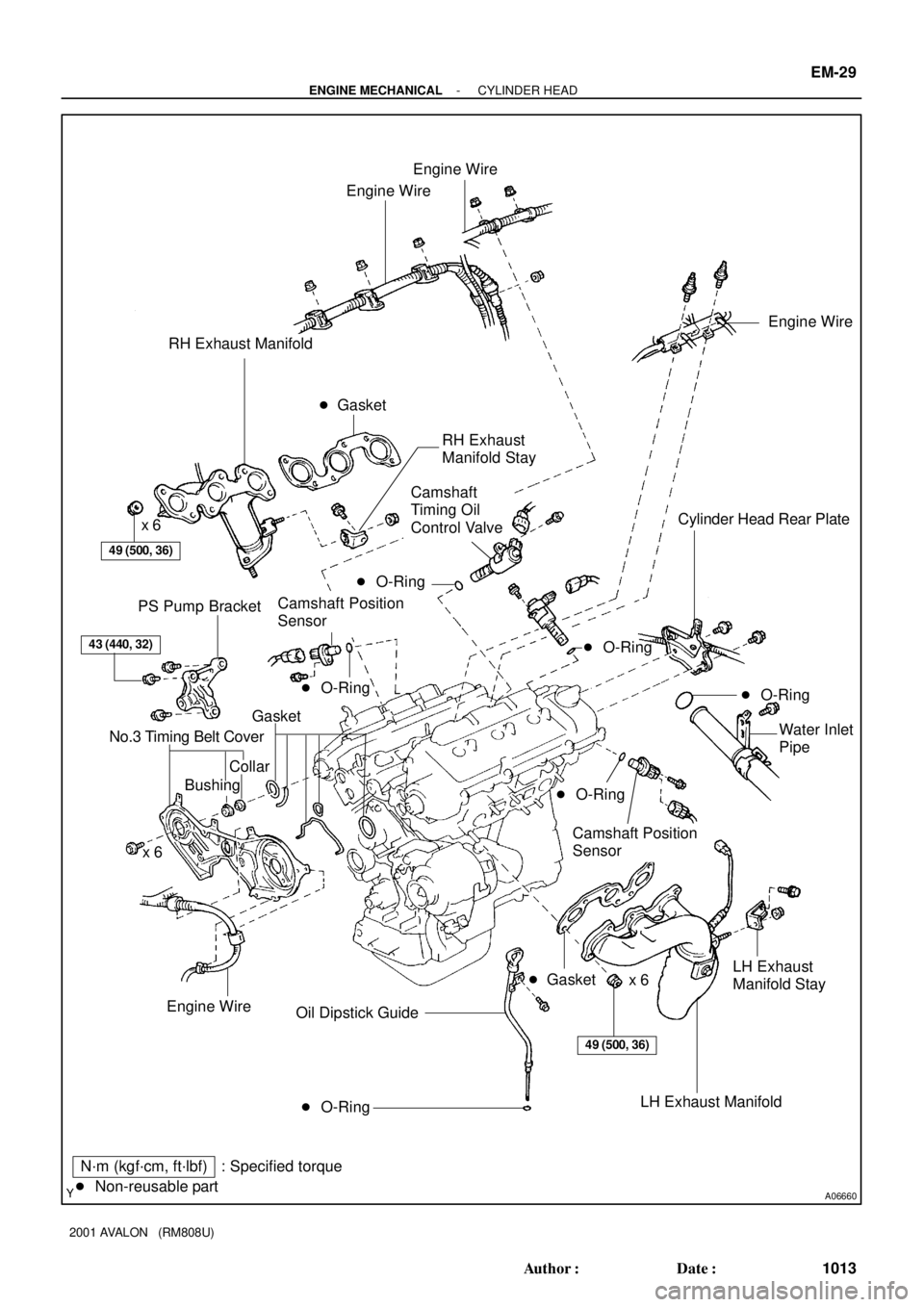
A06660
Engine Wire
Engine Wire
RH Exhaust Manifold
49 (500, 36)
x 6Cylinder Head Rear Plate
PS Pump Bracket
43 (440, 32)
Gasket
No.3 Timing Belt Cover
CollarWater Inlet
Pipe
x 6
� O-Ring Oil Dipstick Guide
N´m (kgf´cm, ft´lbf) : Specified torque
� Non-reusable part� Gasket
Engine Wire
Engine Wire
49 (500, 36)
Bushing
Camshaft Position
Sensor
LH Exhaust
Manifold Stay
x 6
� Gasket
� O-Ring
� O-Ring
LH Exhaust Manifold
� O-Ring
Camshaft
Timing Oil
Control Valve
Camshaft Position
SensorRH Exhaust
Manifold Stay
� O-Ring
� O-Ring
- ENGINE MECHANICALCYLINDER HEAD
EM-29
1013 Author�: Date�:
2001 AVALON (RM808U)
Page 1342 of 1897

11. INSTALL RH EXHAUST MANIFOL")
A06661
Manifold
Stay
A07283
New O-Ring
A07281
Manifold
Stay
A05188Inlet PipeRear
Plate
EM-66
- ENGINE MECHANICALCYLINDER HEAD
1050 Author�: Date�:
2001 AVALON (RM808U)
11. INSTALL RH EXHAUST MANIFOLD
(a) Install a new gasket and the exhaust manifold with the 6
nuts. Uniformly tighten the nuts in several passes.
Torque: 49 N´m (500 kgf´cm, 36 ft´lbf)
(b) Install the exhaust manifold stay with the bolt and nut. Al-
ternately tighten the bolt and nut.
Torque: 34 N´m (350 kgf´cm, 25 ft´lbf)
(c) Connect the A/F sensor connector.
12. INSTALL OIL DIPSTICK AND GUIDE
(a) Install a new O-ring to the dipstick guide.
(b) Apply soapy water to the O-ring.
(c) Push in the dipstick guide end into the guide hole of the
No.1 oil pan.
(d) Install the dipstick guide with the bolt.
Torque: 8 N´m (80 kgf´cm, 69 in.´lbf)
(e) Install the dipstick.
13. INSTALL LH EXHAUST MANIFOLD
(a) Install a new gasket and the exhaust manifold with the 6
nuts. Uniformly tighten the nuts in several passes.
Torque: 49 N´m (500 kgf´cm, 36 ft´lbf)
(b) Install the exhaust manifold stay with the bolt and nut. Al-
ternately tighten the bolt and nut.
Torque: 34 N´m (350 kgf´cm, 25 ft´lbf)
(c) Connect the A/F sensor connector.
14. INSTALL WATER INLET PIPE
(a) Install a new O-ring to the water inlet pipe.
(b) Apply soapy water to the O-ring.
(c) Connect the water inlet pipe to the water inlet.
(d) Install the bolt holding the water inlet pipe to the cylinder
head.
Torque: 19.5 N´m (200 kgf´cm, 14 ft´lbf)
15. INSTALL CYLINDER HEAD REAR PLATE
Torque: 8 N´m (80 kgf´cm, 69 in.´lbf)
16. INSTALL ENGINE WIRE PROTECTOR
17. INSTALL CAMSHAFT TIMING OIL CONTROL VALVES
18. INSTALL CAMSHAFT POSITION SENSORS
19. INSTALL NO.3 TIMING BELT COVER
(a) Check that the timing belt cover gaskets have no cracks
or peeling, etc.
If the gaskets have cracks or peeling etc., replace them using
these steps:
�Using a screwdriver and gasket scraper, remove all
the old gasket material.
Page 1343 of 1897

L = 180 mm (7.09 in.)L = 72 mm (2.83 in.)
L = 335 mm (13.19 in.)L = 180 mm
(7.09 in.)
L = Length Join
LineJoin
Line
Z14262New Gasket
- ENGINE MECHANICALCYLINDER HEAD")
A05194
L = 133 mm (5.24 in.)
L = 180 mm (7.09 in.)L = 72 mm (2.83 in.)
L = 335 mm (13.19 in.)L = 180 mm
(7.09 in.)
L = Length Join
LineJoin
Line
Z14262New Gasket
- ENGINE MECHANICALCYLINDER HEAD
EM-67
1051 Author�: Date�:
2001 AVALON (RM808U)
�Thoroughly clean all components to remove all the
loose material.
�Remove the backing paper from a new gasket and
install the gasket evenly to the part of the timing belt
cover shaded black in the illustration.
NOTICE:
When joining 2 gaskets, do not leave a gap between them.
Cut off any excess gasket.
�After installing the gasket, press down on it so that
the adhesive firmly sticks to the timing belt cover.
(b) Install the timing belt cover with the 6 bolts.
Torque: 8.5 N´m (85 kgf´cm, 74 in.´lbf)
(c) Install the 3 engine wire clamps to the timing belt cover.
20. INSTALL NO.2 IDLER PULLEY (See page EM-21)
21. INSTALL CAMSHAFT TIMING PULLEYS
(See page EM-21)
22. INSTALL TIMING BELT (See page EM-21)
23. INSTALL SPARK PLUGS
24. INSTALL IGNITION COILS
25. INSTALL WATER OUTLET
(a) Install 2 new gaskets.
(b) Connect the water outlet to the bypass hose.
(c) Install the water outlet with the 2 bolts, 2 nuts and 2 plate
washers. Alternately tighten the bolts and nuts.
Torque: 15 N´m (150 kgf´cm, 11 ft´lbf)
NOTICE:
Do not scratch the seal surface of the water outlet with the
stud bolt.
(d) Connect the ECT sender gauge connector.
(e) Connect the ECT sensor connector.
(f) Connect the ground strap connector.
(g) Connect the upper radiator hose.
(h) Connect the engine coolant reservoir hose.
Page 1349 of 1897

(k) (l)
- ENGINE MECHANICALCYLINDER HEAD
EM-31
1015 Author�: Date�:
2001 AVALON (RM808U)
REMOVAL
NOTICE:
Do not remove or install the camshaft timing g")
EM0ZE-02
A10518
5 mm
Hexagon
Wrench
A06658
(j)
(k) (l)
- ENGINE MECHANICALCYLINDER HEAD
EM-31
1015 Author�: Date�:
2001 AVALON (RM808U)
REMOVAL
NOTICE:
Do not remove or install the camshaft timing gear (VVT-i)
beside changing VVT-i or the camshaft.
1. DRAIN ENGINE COOLANT
2. REMOVE RH FENDER APRON SEAL
3. REMOVE GENERATOR DRIVE BELT
(See page CH-6)
4. REMOVE PS PUMP (See page SR-27)
5. REMOVE FRONT EXHAUST PIPE (See page EM-72)
6. REMOVE V-BANK COVER
(a) Using a 5 mm hexagon wrench, remove the 3 cap nuts.
(b) Loosen the V-bank cover fastener counterclockwise.
(c) Remove the V-bank cover.
7. REMOVE AIR CLEANER HOSE WITH RESONATOR
8. REMOVE AIR INTAKE CHAMBER ASSEMBLY
(a) Disconnect the accelerator cable.
(b) Disconnect the throttle cable.
(c) Disconnect the throttle position sensor connector.
(d) Disconnect the IAC valve connector.
(e) Disconnect the No.1 VSV connector for the ACIS.
(f) Disconnect the No.2 VSV connector for the ACIS.
(g) Disconnect the VSV connector for the EVAP.
(h) Disconnect the DLC1 from the bracket on the intake air
control valve.
(i) Remove the 2 nuts, and disconnect the PS pressure tube
from the No.1 engine hanger.
(j) Disconnect the PCV hose from the PCV valve on the RH
cylinder head.
(k) Disconnect the ground strap and cable from the intake air
control valve for the ACIS.
(l) Disconnect the ground cable from the air intake chamber.