Page 3 of 1897
AC2GJ-01
I12984
3931: Bulb
- AIR CONDITIONINGAIR CONDITIONING CONTROL ASSEMBLY (Auto A/C)
AC-75
1997 Author�: Date�:
2001 AVALON (RM808U)
INSPECTION
1. INSPECT ILLUMINATION OPERATION
Connect the positive (+) lead from the battery to terminal 31 and
the negative (-) lead to terminal 39, then check that the illumina-
tion lights up.
If there is bulb not light up, replace the bulb only. If all bulbs do
not light up, replace the A/C control panel.
2. INSPECT A/C CONTROL AMPLIFIER CIRCUIT
(See page DI-759)
Page 6 of 1897

AC-77
1999 Author�: Date�:
2001 AVALON (RM808U)
AIR CONDITIONING AMPLIFIER
(Manual A/C)
ON-VEHICLE INSPECTION
INSPECT A/C A")
I12987
AC2GL-01
- AIR CONDITIONINGAIR CONDITIONING AMPLIFIER (Manual A/C)
AC-77
1999 Author�: Date�:
2001 AVALON (RM808U)
AIR CONDITIONING AMPLIFIER
(Manual A/C)
ON-VEHICLE INSPECTION
INSPECT A/C AMPLIFIER CIRCUIT
(a) Remove the multi display with connectors still connected.
(b) Inspect wire harness side connector from the back side,
as shown in the chart below.
Test conditions:
�Running engine at idle speed
�A/C switch ON
�Temperature control dial ºMAX COOLº position
�Blower speed control switch at ºHIº position
�Set on manifold gauge set
Tester connectionConditionSpecified condition
Refrigerant pressure at 196 - 3,140 kPaBelow 1.0 V
1 - GroundRefrigerant pressure less than 196 kPa or more
than 3,140 kPaBattery positive voltage
2 - GroundConstantPulse generation
5 - GroundA/C switch ONBattery positive voltage
7 - GroundEvaporator temperature at 25 °C (77 °F)Approx. 1.5 kW
8G dA/C switch ONBattery positive voltage8 - GroundA/C switch OFFBelow 1.0 V
9G dA/C switch ONBelow 2.0 V9 - GroundA/C switch OFFNo voltage
10 G dConstantBattery positive voltage10 - GroundEngine speed at idle-up speedBelow 1.0 V
11 G dA/C switch OFFBattery positive voltage11 - GroundA/C switch ONBelow 0.7 V
11 G dMagnetic clutch is engagedBelow 1.0 V11 - GroundMagnetic clutch is not engagedBattery positive voltage
If the circuit is not as specified, inspect the circuits connected
to other parts.
Page 36 of 1897
AC2G8-01
I12927
N16762
21 AC-56
- AIR CONDITIONINGBLOWER MOTOR
1978 Author�: Date�:
2001 AVALON (RM808U)
BLOWER MOTOR
INSPECTION
1. REMOVE GLOVE COMPARTMENT PARTS
(See page BO-90)
2. REMOVE BLOWER MOTOR
(a) Disconnect the connector.
(b) Remove the 3 screws and blower motor.
3. INSPECT BLOWER MOTOR OPERATION
Connect the positive (+) lead from the battery to terminal 2 and
negative (-) lead to terminal 1, then check that the motor opera-
tions smoothly.
If operation is not as specified, replace the blower motor.
4. INSTALL BLOWER MOTOR
(a) Install the blower motor with the 3 screws.
(b) Connect the connector.
5. INSTALL GLOVE COMPARTMENT PARTS
(See page BO-97)
Page 41 of 1897
AC2G3-01
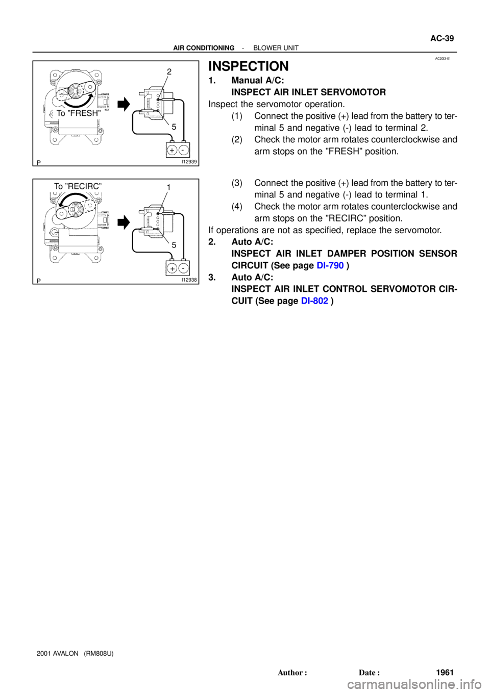
I12939
- +
To ºFRESHº
2
5
I12938
- +
To ºRECIRCº1
5
- AIR CONDITIONINGBLOWER UNIT
AC-39
1961 Author�: Date�:
2001 AVALON (RM808U)
INSPECTION
1. Manual A/C:
INSPECT AIR INLET SERVOMOTOR
Inspect the servomotor operation.
(1) Connect the positive (+) lead from the battery to ter-
minal 5 and negative (-) lead to terminal 2.
(2) Check the motor arm rotates counterclockwise and
arm stops on the ºFRESHº position.
(3) Connect the positive (+) lead from the battery to ter-
minal 5 and negative (-) lead to terminal 1.
(4) Check the motor arm rotates counterclockwise and
arm stops on the ºRECIRCº position.
If operations are not as specified, replace the servomotor.
2. Auto A/C:
INSPECT AIR INLET DAMPER POSITION SENSOR
CIRCUIT (See page DI-790)
3. Auto A/C:
INSPECT AIR INLET CONTROL SERVOMOTOR CIR-
CUIT (See page DI-802)
Page 45 of 1897

1980 Author�: Date�:
2001 AVALON (RM808U)
BLOWER MOTOR LINEAR
CONTROLLER (Auto A/C)
INSPECTION
1. REM")
AC2GA-01
I12967
I03539
1 2 3 4 AC-58
- AIR CONDITIONINGBLOWER MOTOR LINEAR CONTROLLER (Auto A/C)
1980 Author�: Date�:
2001 AVALON (RM808U)
BLOWER MOTOR LINEAR
CONTROLLER (Auto A/C)
INSPECTION
1. REMOVE GLOVE COMPARTMENT PARTS
(See page BO-90)
2. REMOVE BLOWER MOTOR LINEAR CONTROLLER
(a) Disconnect the connector.
(b) Remove the 2 screws and controller.
3. INSPECT BLOWER MOTOR LINEAR CONTROLLER
CIRCUIT
Connect the connector to the controller and inspect the wire
harness side connector from the back side, as shown in the
chart.
Test conditions:
�Turn ignition switch to ON
�Operate blower motor
Tester connectionConditionSpecified conditions
1 - GroundConstantContinuity
2 - GroundConstantBattery positive voltage
2 - GroundTurn ignition switch to LOCK or ACCNo voltage
If the circuit is as specified, try to replace the controller with a
new one. If the circuit is not as specified, inspect the circuits
connected to other parts.
4. INSTALL BLOWER MOTOR LINEAR CONTROLLER
(a) Install the blower motor linear controller with the 2 screws.
(b) Connect the connector.
5. INSTALL GLOVE COMPARTMENT PARTS
(See page BO-97)
Page 51 of 1897

COMPRESSOR AND MAGNETIC
CLUTCH
ON-VEHICLE INSPECTION
1. INSPECT COMPRESS")
AC2G4-01
I12297
12
I12298
3 AC-42
- AIR CONDITIONINGCOMPRESSOR AND MAGNETIC CLUTCH
1964 Author�: Date�:
2001 AVALON (RM808U)
COMPRESSOR AND MAGNETIC
CLUTCH
ON-VEHICLE INSPECTION
1. INSPECT COMPRESSOR FOR METALLIC SOUND
Check there is abnormal metallic sound from the compressor
when the A/C switch is ON.
If abnormal metallic sound is heard, replace the compressor as-
sembly.
2. INSPECT REFRIGERANT PRESSURE
(See page AC-3)
3. INSPECT VISUALLY FOR LEAKAGE OF REFRIGER-
ANT
Using a gas leak detector, check for leakage of refrigerant.
If there is any leakage, replace the compressor assembly.
4. INSPECT COMPRESSOR LOCK SENSOR RESIS-
TANCE
(a) Disconnect the connector.
(b) Measure resistance between terminals 1 and 2.
Standard resistance: 65 - 125 W at 20 °C (68 °F)
If resistance is not as specified, replace the sensor.
5. CHECK FOR LEAKAGE OF GREASE FROM CLUTCH
BEARING
6. CHECK FOR SIGNS OF OIL ON PRESSURE PLATE OR
ROTOR
7. INSPECT MAGNETIC CLUTCH BEARING FOR NOISE
(a) Start engine.
(b) Check for abnormal noise from the compressor when the
A/C switch is OFF.
If abnormal noise is being emitted, replace the magnetic clutch.
8. INSPECT MAGNETIC CLUTCH OPERATION
(a) Disconnect the connector.
(b) Connect the positive (+) lead from the battery to terminal
4 and the negative (-) lead to the body ground.
(c) Check that the magnetic clutch energized.
If operation is not as specified, replace the magnetic clutch.
Page 52 of 1897
AC1N3-02
N04963
Dial Indicator
- AIR CONDITIONINGCOMPRESSOR AND MAGNETIC CLUTCH
AC-49
1971 Author�: Date�:
2001 AVALON (RM808U)
REASSEMBLY
Reassembly is in the reverse order of disassembly (See
page AC-46).
AFTER REASSEMBLY, CHECK MAGNETIC CLUTCH
CLEARANCE
(a) Set the dial indicator to the pressure plate of the magnetic
clutch.
(b) Connect the magnetic clutch lead wire to the positive (+)
terminal of the battery.
(c) Check the clearance between the pressure plate and ro-
tor when connecting the negative (-) terminal to the bat-
tery.
Standard clearance:
0.5 ± 0.15 mm (0.020 ± 0.0059 in.)
If the clearance is not within the standard, adjust the clearance
using shims to obtain the standard.
Shim thickness:
0.1 mm (0.004 in.)
0.3 mm (0.012 in.)
0.5 mm (0.020 in.)
Page 53 of 1897
AC1N1-02
I12935
P19978
N20259
AC-44
- AIR CONDITIONINGCOMPRESSOR AND MAGNETIC CLUTCH
1966 Author�: Date�:
2001 AVALON (RM808U)
REMOVAL
1. RUN ENGINE AT IDLE SPEED WITH A/C ON FOR
APPROX. 10 MINUTES
2. STOP ENGINE
3. DISCONNECT NEGATIVE (- ) TERMINAL CABLE
FROM BATTERY
4. DISCHARGE REFRIGERANT FROM REFRIGERATION
SYSTEM
5. REMOVE DRIVE BELT
(See page AC-18)
6. DISCONNECT DISCHARGE AND SUCTION HOSES
Remove the 2 nuts and disconnect the both hoses.
NOTICE:
Cap the open fittings immediately to keep moisture or dirt
out of the system.
7. REMOVE GENERATOR
(a) Disconnect the generator connector.
(b) Remove the nut, and disconnect the generator wire.
(c) Disconnect the wire harness from the clamp.
(d) Remove the pivot bolt, adjusting lock bolt and generator.
8. REMOVE COMPRESSOR
(a) Disconnect the connector.
(b) Disconnect the wire harness clamp.
(c) Remove the 2 bolts, nut and drive belt adjusting bar
bracket.