Page 1711 of 1897

RS-47
1567 Author�: Date�:
2001 AVALON (RM808U)
HINT:
The airbag")
AB0163
Wire Harness
Diameter
Stripped Wire Harness Section
- SUPPLEMENTAL RESTRAINT SYSTEMSIDE AIRBAG ASSEMBLY (Power Adjuster Type)
RS-47
1567 Author�: Date�:
2001 AVALON (RM808U)
HINT:
The airbag deploys simultaneously as the LED of SST activa-
tion switch lights up.
2. DEPLOYMENT WHEN DISPOSING OF SIDE AIRBAG
ASSEMBLY
NOTICE:
�When disposing of the side airbag assembly only,
never use the customer's vehicle to deploy the air-
bag.
�Be sure to follow the procedure given below when de-
ploying the airbag.
HINT:
Have a battery ready as the power source to deploy the airbag.
(a) Remove the seatback assembly (See page RS-42).
(b) Remove the side airbag assembly from the seatback as-
sembly.
(1) Remove the hog rings.
(2) Release the seatback cover hook from the seat-
back frame.
(3) Remove the 2 bolts and side airbag assembly.
CAUTION:
When storing the side airbag assembly, keep the upper sur-
face of the airbag deployment side facing upward.
(c) Using a service-purpose wire harness, tie down the side
airbag assembly to the tire.
Wire harness: Stripped wire harness section
1.25 mm
2
or more (0.0019 in2. or more)
CAUTION:
If a wire harness which is too thin or some other thing is
used to tie down the side airbag assembly, it may be
snapped by the shock when the airbag is deployed. This is
highly dangerous. Always use a wire harness for vehicle
use which is at least 1.25 mm
2 (0.0019 in2.).
HINT:
To calculate the square of the stripped wire harness section-
Square = 3.14 x (Diameter)
2 divided by 4
Page 1712 of 1897

1568 Author�: Date�:
2001 AVALON (RM808U)
(1) Install the 2 nuts to the side a")
H11966
H11967
H11968
AB0158
SSTBattery RS-48
- SUPPLEMENTAL RESTRAINT SYSTEMSIDE AIRBAG ASSEMBLY (Power Adjuster Type)
1568 Author�: Date�:
2001 AVALON (RM808U)
(1) Install the 2 nuts to the side airbag assembly.
(2) Wind the wire harness around the stud bolts of the
side airbag assembly as shown in the illustration.
(3) Position the side airbag assembly inside the tire
with the airbag deployment direction facing inside.
Tire size: Must exceed the following dimensions-
Width: 185 mm (7.28 in.)
Inner diameter: 360 mm (14.17 in.)
CAUTION:
�Make sure the wire harness is tight. It is very danger-
ous when a loose wire harness results in the side air-
bag assembly coming free due to the shock from the
airbag deploying.
�Always tie down the side airbag assembly with the
airbag deployment side facing inside.
NOTICE:
The tire will be marked by the airbag deployment, so when
disposing of the airbag use a redundant tire.
(d) Check functioning of the SST (See step 1-(a) on page
RS-17).
SST 09082-00700
Page 1713 of 1897

R05403
H0133710 m (33 ft) or more SSTBattery
Side Airbag
Assembly
H00544
- SUPPLEMENTAL RESTRAINT SYSTEMSIDE AIRBAG ASSEMBLY (Power Adjuster Type)
RS-49
1569 Author�: Date�:")
H01336
Tires
(5 or More)
R05403
H0133710 m (33 ft) or more SSTBattery
Side Airbag
Assembly
H00544
- SUPPLEMENTAL RESTRAINT SYSTEMSIDE AIRBAG ASSEMBLY (Power Adjuster Type)
RS-49
1569 Author�: Date�:
2001 AVALON (RM808U)
(e) Place the tires.
(1) Place at least 2 tires under the tire to which the side
airbag assembly is tied.
(2) Place at least 2 tires over the tire to which the side
airbag assembly is tied. The top tire should have the
wheel installed.
(3) Tie the tires together with 2 wire harness.
CAUTION:
Make sure that the wire harness are tight. It is very danger-
ous when loose wire harness results in the tires coming
free due to the shock from the airbag deploying.
HINT:
Place the SST connector and wire harness inside tires. Secure
at least 1 m (3 ft) of slack for the wire harness.
(f) Install the SST.
Connect the connectors of the 2 SST to the side airbag
assembly connector.
SST 09082-00700, 09082-00750
NOTICE:
To avoid damaging the SST connector and wire harness,
do not lock the secondary lock of the twin lock. Also, se-
cure some slack for the SST wire harness inside the tire.
(g) Deploy the airbag.
(1) Connect the SST red clip to the battery positive (+)
terminal and the black clip to the battery negative
(-) terminal.
(2) Check that no one is within 10 m (33 ft) area around
the tire which the side airbag assembly is tied to.
(3) Press the SST activation switch and deploy the air-
bag.
HINT:
The airbag deploys simultaneously as the LED of the SST ac-
tivation switch lights up.
(h) Dispose of the side airbag assembly.
CAUTION:
�The side airbag assembly is very hot when the airbag
is deployed, so leave it alone for at least 30 minutes
after deployment.
�Use gloves and safety glasses when handling a side
airbag assembly with the deployed airbag.
�Do not apply water etc. to a side airbag assembly with
the deployed airbag.
Page 1714 of 1897

1570 Author�: Date�:
2001 AVALON (RM808U)
�Always wash your hands with water after completing
the operation.
(")
H00544
RS-50
- SUPPLEMENTAL RESTRAINT SYSTEMSIDE AIRBAG ASSEMBLY (Power Adjuster Type)
1570 Author�: Date�:
2001 AVALON (RM808U)
�Always wash your hands with water after completing
the operation.
(1) Remove the side airbag assembly from the tire.
(2) Place the side airbag assembly in a vinyl bag, tie the
end tightly and dispose of it in the same way as oth-
er general parts disposal.
3. DEPLOYMENT WHEN DISPOSING OF SIDE AIRBAG
ASSEMBLY WITH AIRBAG DEPLOYED IN COLLISION
Dispose of the side airbag assembly.
CAUTION:
�The side airbag assembly is very hot when the airbag
is deployed, so leave it alone for at least 30 minutes
after deployment.
�Use gloves and safety glasses when handling a side
airbag assembly with the deployed airbag.
�Do not apply water etc. to a side airbag assembly with
the deployed airbag.
�Always wash your hands with water after completing
the operation.
(1) Remove the side airbag assembly from the seat
(See page RS-42 and see step 2. on page RS-45).
(2) Place the side airbag assembly in a vinyl bag, tie the
end tightly and dispose of it in the same way as oth-
er general parts disposal.
Page 1815 of 1897
F08857
SR0EG-05
F08858
SR-8
- STEERINGSTEERING WHEEL
1471 Author�: Date�:
2001 AVALON (RM808U)
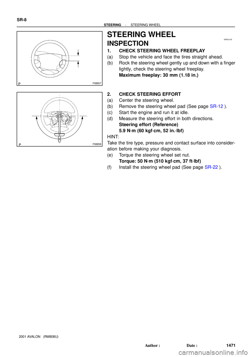
STEERING WHEEL
INSPECTION
1. CHECK STEERING WHEEL FREEPLAY
(a) Stop the vehicle and face the tires straight ahead.
(b) Rock the steering wheel gently up and down with a finger
lightly, check the steering wheel freeplay.
Maximum freeplay: 30 mm (1.18 in.)
2. CHECK STEERING EFFORT
(a) Center the steering wheel.
(b) Remove the steering wheel pad (See page SR-12).
(c) Start the engine and run it at idle.
(d) Measure the steering effort in both directions.
Steering effort (Reference)
5.9 N´m (60 kgf´cm, 52 in.´lbf)
HINT:
Take the tire type, pressure and contact surface into consider-
ation before making your diagnosis.
(e) Torque the steering wheel set nut.
Torque: 50 N´m (510 kgf´cm, 37 ft´lbf)
(f) Install the steering wheel pad (See page SR-22).