Page 97 of 1897
AT3412
AX03Z-05
AX-42
- AUTOMATIC TRANSAXLEAUTOMATIC TRANSAXLE UNIT
1332 Author�: Date�:
2001 AVALON (RM808U)
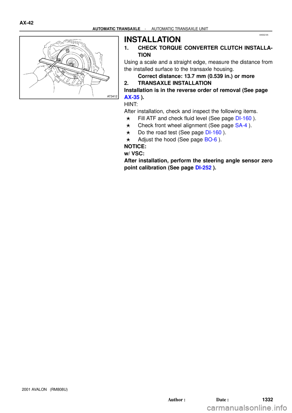
INSTALLATION
1. CHECK TORQUE CONVERTER CLUTCH INSTALLA-
TION
Using a scale and a straight edge, measure the distance from
the installed surface to the transaxle housing.
Correct distance: 13.7 mm (0.539 in.) or more
2. TRANSAXLE INSTALLATION
Installation is in the reverse order of removal (See page
AX-35).
HINT:
After installation, check and inspect the following items.
�Fill ATF and check fluid level (See page DI-160).
�Check front wheel alignment (See page SA-4).
�Do the road test (See page DI-160).
�Adjust the hood (See page BO-6).
NOTICE:
w/ VSC:
After installation, perform the steering angle sensor zero
point calibration (See page DI-252).
Page 100 of 1897
Q06530
Q10038
D07216
Q10037
- AUTOMATIC TRANSAXLEAUTOMATIC TRANSAXLE UNIT
AX-37
1327 Author�: Date�:
2001 AVALON (RM808U)
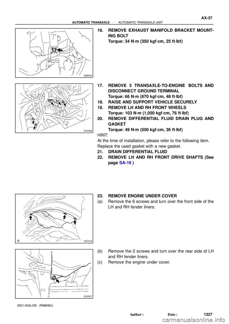
16. REMOVE EXHAUST MANIFOLD BRACKET MOUNT-
ING BOLT
Torque: 34 N´m (350 kgf´cm, 25 ft´lbf)
17. REMOVE 5 TRANSAXLE-TO-ENGINE BOLTS AND
DISCONNECT GROUND TERMINAL
Torque: 66 N´m (670 kgf´cm, 48 ft´lbf)
18. RAISE AND SUPPORT VEHICLE SECURELY
19. REMOVE LH AND RH FRONT WHEELS
Torque: 103 N´m (1,050 kgf´cm, 76 ft´lbf)
20. REMOVE DIFFERENTIAL FLUID DRAIN PLUG AND
GASKET
Torque: 49 N´m (500 kgf´cm, 36 ft´lbf)
HINT:
At the time of installation, please refer to the following item.
Replace the used gasket with a new gasket.
21. DRAIN DIFFERENTIAL FLUID
22. REMOVE LH AND RH FRONT DRIVE SHAFTS (See
page SA-16)
23. REMOVE ENGINE UNDER COVER
(a) Remove the 6 screws and turn over the front side of the
LH and RH fender liners.
(b) Remove the 2 screws and turn over the rear side of LH
and RH fender liners.
(c) Remove the engine under cover.
Page 106 of 1897
Q00394
SST
AX03S-05
Q06348
SST
Q00238
SST AX-14
- AUTOMATIC TRANSAXLEDIFFERENTIAL OIL SEAL
1304 Author�: Date�:
2001 AVALON (RM808U)
DIFFERENTIAL OIL SEAL
ON-VEHICLE REPAIR
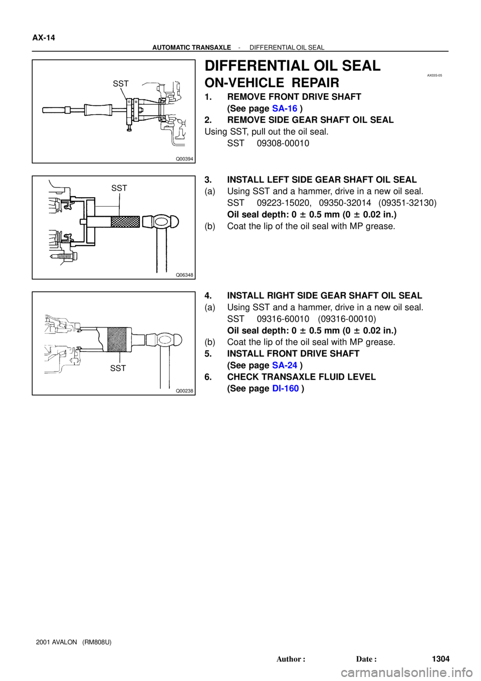
1. REMOVE FRONT DRIVE SHAFT
(See page SA-16)
2. REMOVE SIDE GEAR SHAFT OIL SEAL
Using SST, pull out the oil seal.
SST 09308-00010
3. INSTALL LEFT SIDE GEAR SHAFT OIL SEAL
(a) Using SST and a hammer, drive in a new oil seal.
SST 09223-15020, 09350-32014 (09351-32130)
Oil seal depth: 0 ± 0.5 mm (0 ± 0.02 in.)
(b) Coat the lip of the oil seal with MP grease.
4. INSTALL RIGHT SIDE GEAR SHAFT OIL SEAL
(a) Using SST and a hammer, drive in a new oil seal.
SST 09316-60010 (09316-00010)
Oil seal depth: 0 ± 0.5 mm (0 ± 0.02 in.)
(b) Coat the lip of the oil seal with MP grease.
5. INSTALL FRONT DRIVE SHAFT
(See page SA-24)
6. CHECK TRANSAXLE FLUID LEVEL
(See page DI-160)
Page 144 of 1897

VALVE BODY ASSEMBLY
ON-VEHICLE REPAIR
1. CLEAN TRANSAXLE EXTER")
AX05D-03
AT3785
AT0103
D01019
Q05728
Connector AX-6
- AUTOMATIC TRANSAXLEVALVE BODY ASSEMBLY
1296 Author�: Date�:
2001 AVALON (RM808U)
VALVE BODY ASSEMBLY
ON-VEHICLE REPAIR
1. CLEAN TRANSAXLE EXTERIOR
To help prevent contamination, clean the exterior of the trans-
axle.
2. DRAIN ATF
Using a hexagon wrench, remove the drain plug and drain the
fluid into the suitable container.
3. REMOVE OIL PAN AND GASKET
NOTICE:
Some fluid will remain in the oil pan.
Remove oil pan bolts, and carefully remove the pan assembly.
Discard the gasket.
4. EXAMINE PARTICLES IN PAN
Remove the magnets and use them to collect any steel chips.
Look at the chips and particles in the pan and magnet carefully
to anticipate what type of wear you will find in the transaxle.
�Steel (magnetic): bearing, gear and plate wear
�Brass (non-magnetic): bushing wear
5. REMOVE OIL STRAINER AND APPLY PIPE BRACKET
(a) Remove the 3 bolts and oil strainer.
NOTICE:
Be careful as oil will come out of the strainer when it is re-
moved.
(b) Remove the 3 bolts and apply pipe bracket.
6. REMOVE OIL PIPE
Pry up both pipe ends with a large screwdriver and remove the
5 pipes.
7. DISCONNECT 3 SOLENOID CONNECTORS
Page 149 of 1897
Z19256
BA
B A
AT3741
AT3785
- AUTOMATIC TRANSAXLEVALVE BODY ASSEMBLY
AX-1 1
1301 Author�: Date�:
2001 AVALON (RM808U)
24. INSTALL OIL STRAINER AND APPLY PIPE BRACKET
Install the oil strainer and apply pipe bracket with the 6 bolts.
Torque:
Bolt A: 10 N´m (100 kgf´cm, 7 ft´lbf)
Bolt B: 11 N´m (110 kgf´cm, 8 ft´lbf)
Bolt length:
Bolt A: 22 mm (0.866 in.)
Bolt B: 53 mm (2.087 in.)
25. INSTALL MAGNET IN PLACE
Install the 3 magnets in the indentations of the oil pan, as shown
in the illustration.
NOTICE:
Make sure that the magnet does not interfere with the oil
pipes.
26. INSTALL OIL PAN AND GASKET
(a) Install the oil pan and a new gasket.
(b) Install the 17 bolts.
Torque: 7.8 N´m (80 kgf´cm, 69 in.´lbf)
27. INSTALL DRAIN PLUG
Install a new gasket and drain plug.
Torque: 49 N´m (500 kgf´cm, 36 ft´lbf)
28. FILL ATF AND CHECK FLUID LEVEL
(See page DI-160)
Page 198 of 1897
No.Wire Connector Side
1
2
3
4
6
7
8
9
10
14
15
16Washer fluid level warning switch
Body ECU
Brake fluid level warning switch
GAUGE Fuse
Lo oil pressure warning switch
ECM
-
TRAC
VSC ECU
Light failure Sensor
-
-
G1
2
3
4
6
7
8
9
10
11
12
13-
Driver's door courtesy switch
DOME Fuse
Cruise ECU
Airbag ECU
ABS&BA&DRAC&VSC ECU
-
Body ECU
Generator L terminal Ignition switch 5 ABS ECU
5 AIR BAG WRN Fuse F
-
- BE-48
- BODY ELECTRICALCOMBINATION METER
1652 Author�: Date�:
2001 AVALON (RM808U)
Page 209 of 1897

I07709
35.63 ± 0.1 W
Slide
rheostat
35.63 ±
0.1 W
Z15789
Warning Light
Ignition
Switch
BatteryWire Harness
N06640
BE1217
Warning Light
Ignition
Switch
Battery
- BODY ELECTRICALCOMBINATION METER
BE-59
1663 Author�: Date�:
2001 AVALON (RM808U)
15. INSPECT ENGINE COOLANT TEMPERATURE SEND-
ER GAUGE RESISTANCE
Connect the wire harness as shown in the illustration, and ad-
just the ammeter pointer to indicate º0º using the slide rheostat,
then read the rheostat indication.
Temperature °C (°F)Resistance (W)
50 (122.0)160 - 240
120 (248.0)17.1 - 21.2
If resistance value is not as specified, replace the engine cool-
ant sender gauge.
16. INSPECT LOW OIL PRESSURE WARNING LIGHT
(a) Disconnect the connector from the warning switch and
ground terminal on the wire harness side connector.
(b) Turn the ignition switch ON, check that the warning light
lights up.
If the warning light does not light up, test the bulb or inspect wire
harness.
17. INSPECT LOW OIL PRESSURE WARNING SWITCH
OPERATION
(a) Check that continuity exists between the terminal and
ground with the engine stopped.
(b) Check that no continuity exists between the terminal and
ground with the engine running.
HINT:
Oil pressure should be over 29 kPa (0.35 kgf/cm
2, 4.3 psi)
If operation is not as specified, replace the switch.
18. INSPECT BRAKE WARNING LIGHT
(a) Disconnect the connector from the brake fluid warning
switch.
(b) Release the parking brake pedal.
(c) Connect the terminals on the wire harness side of the lev-
el warning switch connector.
(d) Start the engine, check that the warning light lights up.
If the warning light does not light up, test the bulb or wire har-
ness.
Page 210 of 1897

19. INSP")
N02346
ON OFF
1 2
Z11183
1
Z15790
Warning Light
Ignition
Switch
BatteryWire Harness Side
123 45
6789101112
BE-60
- BODY ELECTRICALCOMBINATION METER
1664 Author�: Date�:
2001 AVALON (RM808U)
19. INSPECT BRAKE FLUID LEVEL WARNING SWITCH
OPERATION
(a) Remove the reservoir tank cap and strainer.
(b) Disconnect the connector.
(c) Check that no continuity exists between the terminals with
the switch OFF (float up).
(d) Use a siphon, etc. to take fluid out of the reservoir tank.
(e) Check that continuity exists between the terminals with
the switch ON (float down).
(f) Pour the fluid back in the reservoir tank.
If operation is not as specified, replace the switch.
20. INSPECT PARKING BRAKE WARNING SWITCH CON-
TINUITY
(a) Check that continuity exists between terminal and switch
body with the switch ON (switch pin released).
(b) Check that no continuity exists between terminal and
switch body with the switch OFF (switch pin pushed in).
If operation is not as specified, replace the switch or inspect
ground point.
21. INSPECT REAR LIGHTS WARNING LIGHT
(a) Disconnect the connector from the light failure sensor and
ground terminal 4 on the wire harness side connector.
(b) Start the engine, check that the warning light lights up.
If the warning light does not light up, test the bulb or inspect wire
harness.